12 - Transient Analysis
Overview of transient analysis
Minimum requirements to run a transient analysis
Minimum circuit design requirements
Circuit should contain one of the following:
- An independent source with a transient specification (see Table 12-1)
- An initial condition on a reactive element
- A controlled source that is a function of time
Minimum program setup requirements
- From Capture’s PSpice menu, choose New Simulation Profile or Edit Simulation Profile. (If this is a new simulation, enter the name of the profile and click OK.)
The Simulation Settings dialog box appears. - Click the Analysis tab.
- From the Analysis type list box, select Time Domain (Transient).
- Specify the required parameters for the transient analysis you want to run.
- Click OK to save the simulation profile.
- From the PSpice menu, choose Run to start the simulation.
Defining a time-based stimulus
Overview of stimulus generation
Symbols that generate input signals for your circuit can be divided into two categories:
- those whose transient behavior is characterized graphically using the Stimulus Editor
- those whose transient behavior is characterized by manually defining their properties within Capture
These symbols are summarized in Table 12-1.
| Specified by... | Symbol name | Description |
|---|---|---|
|
Using the Stimulus Editor |
VSTIM |
voltage source |
|
ISTIM |
current source |
|
|
DIGSTIM1 DIGSTIM2 DIGSTIM4 DIGSTIM8 DIGSTIM16 DIGSTIM32 |
digital stimuli Digital stimuli are not supported in PSpice A/D.
|
|
|
Defining symbol attribute |
VSRC |
voltage sources |
|
ISRC |
current sources |
|
|
DIGCLOCK |
digital clock signal |
|
|
STIM1 |
digital stimuli |
|
|
FILESTIM1 FILESTIM2 FILESTIM4 FILESTIM8 FILESTIM16 FILESTIM32 |
digital file stimuli Digital stimuli are not supported in PSpice A/D.
|
To use any of these source types, you must place the symbol in your schematic and then define its transient behavior.
Each property-characterized stimulus has a distinct set of attributes depending upon the kind of transient behavior it represents. For VPWL_F_xxx, IPWL_F_xxx, and FSTIM, a separate file contains the stimulus specification.
As an alternative, the Stimulus Editor automates the process of defining the transient behavior of stimulus devices. The Stimulus Editor allows you to create analog stimuli which generate sine wave, repeating pulse, exponential pulse, single-frequency FM, and piecewise linear waveforms. It also facilitates creating digital stimuli with complex timing relations. This applies to both stimulus symbols placed in your schematic as well as new ones that you might create.
The stimulus specification created using the Stimulus Editor is saved to a file, automatically configured into the schematic, and associated with the corresponding VSTIM, ISTIM, or DIGSTIM part instance or symbol definition.
Using CheckPoints
You can save the state of a transient simulation at different moments as CheckPoints. You can specify any of the CheckPoints as a restart point and rerun the simulation from that point. As a result, you can avoid running a long simulation from the start and run only the portion that is expected to have the outputs of interest. For example, you simulate an SMPS design and determine a convergence error towards the end of the simulation. You can change design settings and rerun the portion of simulation that throws the error instead of running the simulation from the beginning.
To use CheckPoints:
- Specify the CheckPoints.
- Run the initial analysis.
- Specify the restart point.
- Restart the analysis.
Specifying CheckPoints
You need to define the following for CheckPoints:
- Simulation time interval: The interval in simulation time between two CheckPoints. The default unit is seconds (s) but you can also specify the time in all standard scale modifiers, such as microseconds (ms) and nanoseconds (ns).
- Real time interval: The interval between two CheckPoints in real time. The default is minutes (min) but you can also specify intervals in hours (hrs).
- Time points: Specific times when CheckPoints are created.
In case of digital circuits, CheckPoint will not be generated at a timepoint if there are no events. For example, if a digital circuit changes state from 0 to 1 at a specified timepoint, a checkpoint will be generated. But if there is no transition, checkpoint will not be generated at that timepoint. - Directory location: The location where CheckPoint data is stored. The default location is the transient simulation profile directory.
You can define CheckPoints either from the Simulation Settings dialog box or by editing the circuit file (.cir).
Using the Simulation Settings dialog box
To define CheckPoints using the simulation settings dialog box:
- Open the Simulation Settings dialog box.
- In the Analysis tab, select Save Check Point.
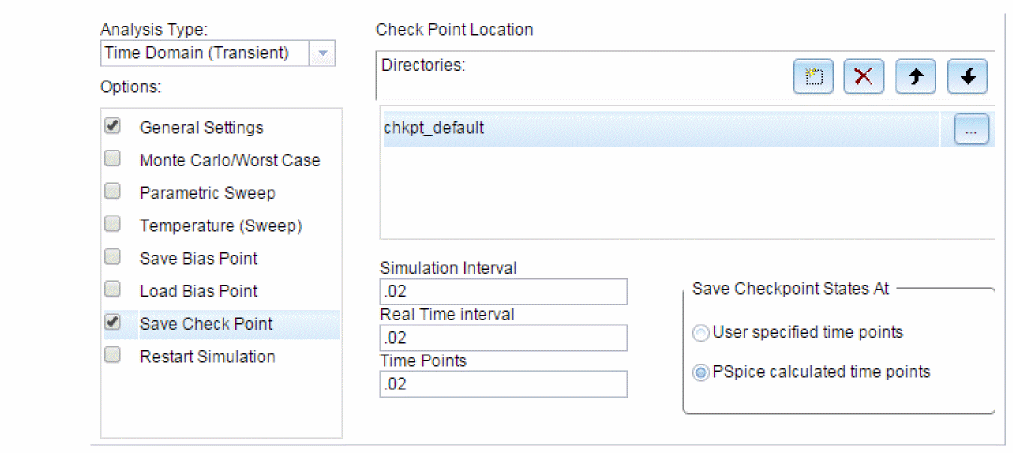
- In the Check Point Location box, specify the location where the CheckPoint data will be stored. You can specify more than one directory and change the order of directories in the Directories field using the buttons.
- In the Simulation Interval box, specify the interval in seconds.
- In the Real Time Interval box, specify the real time in minutes or hours.
- In the Time Points box, specify the time points where CheckPoints are to be created.
The time points must be separated by either space or comma.
Editing the Circuit File
You can edit the circuit file to specify CheckPoints. The syntax for CheckPoint is:
.chkpt CheckPoint_name time_interval_type time_interval_value [time_interval_type time_interval_value ][TSTEP 0/1]
The TSTEP values can be:
|
0 |
generate CheckPoints closest to the specified time points using default time step of PSpice engine |
|
1 |
generate CheckPoints at the specified time points |
The value for the parameter time_interval_type cane be:
|
SINT |
Specifies simulation time interval |
|
RINT |
Specifies real time interval |
|
TP |
Specifies time points |
For example, the following specifies a CheckPoint to be saved as D:\simdata\checkset1 with simulation time interval of 1ms, real time interval 10 minutes, and time points 2.5ms and 7.5ms:
.chkpt “D:/simdata/checkset1” SINT 1ms RINT 10min TP 2.5ms,7.5ms
Ensure that you have a transient analysis defined before running the simulation.
Restarting Simulation from a Saved CheckPoint
You might want to restart a simulation from a saved CheckPoint after changing the design. You can view the CheckPoint locations on the traces displayed in the Probe window. This will enable you to choose the CheckPoint to restart the simulation.
You can change the following in the schematic before restarting a simulation:
- Component values
- Parameter values
- Simulation options
- CheckPoint restart options
- Data save options
Before restarting simulations, note that you cannot:- Add or remove components before restarting simulation
- Change device name or order in the circuit file
- Change initial condition of device such as capacitor
- Change multi-analysis options, such as temperature, parameter, or MC sweep
- Topology changes for digital and mixed signal circuits:
- Changes in IO Model
- Changes in IO_LEVEL
- Changes in Timing models
- Changes in minimum time and maximum delay properties
- Change in the stimulus source
Multi analysis options are not supported currently. If you select multi analysis and enable Save Checkpoint option, the simulation will run but Checkpoint states will not be saved.
To restart simulation from a CheckPoint:
- Choose PSpice – Edit Simulation Profile.
- In the Analysis tab, select the Restart Simulation option.
- Ensure that the correct CheckPoint location is selected in the Check Point Location section.
- From the Restart At section, select any one of the following options:
- Simulation Time
- Real Time
- Select the time from the list and click OK.
- Run the simulation.
You can also edit the circuit file to specify the restart point. The syntax for the restart option is:
.restart CheckPoint_name state_number [0/1]
Where,
|
0 |
Original DAT file is overwritten |
|
1 |
Original DAT file is saved as |
You can check the Save Original Dat File option to ensure that the original file is not overwritten.
For example, to restart a simulation from the 20th saved state of the CheckPoint D:/simdata/checkset1:
.restart “D:/simdata/checkset1” state20
The Stimulus Editor utility
The Stimulus Editor is a utility that allows you to quickly set up and verify the input waveforms for a transient analysis. You can create and edit voltage sources, current sources, and digital stimuli for your circuit. Menu prompts guide you to provide the necessary parameters, such as the rise time, fall time, and period of an analog repeating pulse, or the complex timing relations with repeating segments of a digital stimulus. Graphical feedback allows you to quickly verify the waveform. See the Stimulus Editor help for more information about this utility.
Stimulus files
The Stimulus Editor produces a file containing the stimuli with their transient specification. These stimuli are defined as simulator device declarations using the V (voltage source), I (current source), and U STIM (digital stimulus generator) forms. Since the Stimulus Editor produces these statements automatically, you will never have to be concerned with their syntax. However, if you are interested in a detailed description of their syntax, see the descriptions of V and I devices in the Analog Devices chapter and stimulus generator in the Digital Devices chapter of the PSpice A/D Reference Guide.
Configuring stimulus files
The Stimulus files list in the Configuration Files tab of the Simulation Settings dialog box allows you to view the list of stimulus files related to your current schematic.
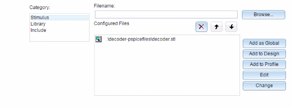
You can also manually add, delete, or change the stimulus file configuration in this tab dialog box. The list box displays all of the currently configured stimulus files. One file is specified per line. Files can be configured as either global to the Capture environment, local to the current design, or only for the current profile. Global files are marked with the ![]() icon before the file name.
icon before the file name.
When starting the Stimulus Editor from Capture, stimulus files are automatically configured (added to the list) as local to the current design. Otherwise, new stimulus files can be added to the list by entering the file name in the Filename text box and then clicking the Add to Profile (profile specific configuration), Add to Design (local configuration) or Add as Global (global configuration) button.
Starting the Stimulus Editor
The Stimulus Editor is fully integrated with Capture and can be run from either the schematic editor or symbol editor.
You can start the Stimulus Editor by doing the following:
- Select one or more stimulus instances in the schematic.
- From the Edit menu, choose PSpice Stimulus.
When you first start the Stimulus Editor, you may need to adjust the scale settings to fit the trace you are going to add. You can use Axis Settings on the Plot menu or the corresponding toolbar button to change the displayed data, the extent of the scrolling region, and the minimum resolution for each of the axes. Displayed Data Range parameters determine what portion of the stimulus data set will be presented on the screen. Extent of Scrolling Region parameters set the absolute limits on the viewable range. Minimum Resolution parameters determine the smallest usable increment (example: if it is set to 1 msec, then you cannot add a data point at 1.5 msec).
Defining stimuli
- Place stimulus part instances from the symbol set: VSTIM, ISTIM and DIGSTIMn (found in the SOURCSTM.OLB part library).
- Click the source instance to select it.
- From the Edit menu, choose PSpice Stimulus to start the Stimulus Editor.
- Fill in the transient specification according to the dialogs and prompts.
Piecewise linear and digital stimuli can be specified by direct manipulation of the input waveform display. - From the File menu, choose Save to save the edits.
- Click Yes to update the schematic.
Example: piecewise linear stimulus
- Open an existing schematic or start a new one.
- From the Place menu, choose Part and browse the
SOURCSTM.OLBpart library file for VSTIM (and select it). - Place the part. It looks like a regular voltage source with an implementation property displayed.
- Click the implementation label and type
Vfirst. This names the stimulus that you are going to create. - If you are working in a new schematic, choose Save from the File menu. This schematic save step is necessary since the schematic name is used to create the default stimulus file name.
- Click the VSTIM part to select it.
- From the Edit menu, choose PSpice Stimulus. This starts the Stimulus Editor and displays the New Stimulus dialog box. You can see that the stimulus already has the name of Vfirst.
- Select PWL in the dialog box and click OK. The cursor looks like a pencil. The message in the status bar at the bottom of the screen lets you know that you are in the process of adding new data points to the stimulus. The left end of the bottom status bar displays the current coordinates of the cursor.
- Move the cursor to (200ns, 1) and click the left mouse button. This adds the point. Notice that there is automatically a point at (0,0). Ignore it for now and continue to add a couple more points to the right of the current one.
- Click-right to stop adding points.
- From the File menu, choose Save.
If you make a mistake or want to make any changes, reshape the trace by dragging any of the handles to a new location. The dragged handle cannot pass any other defined data point.
To delete a point, click its handle and press Delete.
To add additional points, either choose Add Point from the Edit menu, press Alt+A, or click the Add Point toolbar button ![]() .
.
At this point you can return to Capture, edit the current stimulus, or go on to create another.
Example: sine wave sweep
This example creates a 10k sine wave with the amplitude parameterized so that it can be swept during a simulation.
- Open an existing schematic or start a new one.
- Place a VSTIM part on your schematic.
- To name the stimulus, double-click the implementation property and type
Vsin. - Click the VSTIM part to select it.
- From the PSpice menu, choose Edit Stimulus to start the Stimulus Editor.
- Define the stimulus parameter for amplitude:
- From the New Stimulus dialog box, choose Cancel.
- From the Tools menu, choose Parameters.
- Enter
AMP=1in the Definition text box, and click OK. - From the Stimulus menu, choose New or click the New Stimulus button
 in the toolbar.
 - Give the stimulus the name of Vsin.
- Select SIN as the type of stimulus to be created, and click OK.
- Define the other stimulus properties:
- Enter
0for Offset Value. - Enter
{AMP}for Amplitude. The curly braces are required. They indicate that the expression needs to be evaluated at simulation time. - Enter
10kfor Frequency and click OK. - From the File menu, choose Save.
- Click Yes to update the schematic.
- Enter
- Within Capture, place and define the PARAM symbol:
- From the Place menu, choose Part.
- Either browse
SPECIAL.OLBfor the PARAM part or type in the name. - Place the part on your schematic and double-click it.
- Click New to add a new user property.
- Set the value property name to AMP (no curly braces).
- Set the value of the AMP property to 1.
- Set up the parametric sweep and other analyses:
- From the PSpice menu, choose Edit Simulation Profile, and select the Parametric Sweep option.
- Select Global Parameter in the Swept Var. Type frame.
- Select Linear in the Sweep type frame.
- Enter
AMPin the Parameter name text box. - Specify values for the Start Value, End Value, and Increment text boxes.
You can now set up your usual Transient, AC, or DC analysis and run the simulation.
Creating new stimulus symbols
- Use the Capture part editor to edit or create a part with the following properties:
Property Value Implementation Type
PSpice Stimulus
Implementation
Name of the stimulus model
STIMTYPE
Type of stimulus valid values are ANALOG or DIGITAL if this property is nonexistent, the stimulus is assumed to be ANALOG
Editing a stimulus
To edit an existing stimulus
- Start the Stimulus Editor and select File, Open to open the required Stimulus library.
- Double-click the trace name (at the bottom of the X axis for analog and to the left of the Y axis for digital traces.) This opens the Stimulus Attributes dialog box where you can modify the attributes of the stimulus directly and immediately see the effect of the changes.
To edit a PWL stimulus
- Double-click the trace name. This displays the handles for each defined data point.
- Click any handle to select it. To reshape the trace, drag it to a new location. To delete the data point, press Delete.
- To add additional data points, either select Add from the Edit menu or click the Add Point button.
- Right-click to end adding new points.
To select a time and value scale factor for PWL stimuli
- Select the PWL trace by clicking on its name.
- Select Attributes from the Edit menu or click the corresponding toolbar button
 .
.
Deleting and removing traces
To delete a trace from the displayed screen, select the trace name by clicking on its name, then press Delete. This will only erase the display of the trace, not delete it from your file. The trace is still available by selecting Get from the Stimulus menu.
To remove a trace from a file, select Remove from the Stimulus menu.
Manual stimulus configuration
Stimuli can be characterized by manually starting the Stimulus Editor and saving their specifications to a file. These stimulus specifications can then be associated to stimulus instances in your schematic or to stimulus symbols in the symbol library.
To manually configure a stimulus
- Start the Stimulus Editor by choosing the Stimulus Editor icon from the Windows Start menu, installed OrCAD X program group, PSpice Accessories option.
- Open a stimulus file by choosing Open from the File menu. If the file is not found in your current library search path, you are prompted for a new file name.
- Create one or more stimuli to be used in your schematic. For each stimulus:
- Name it whatever you want. This name will be used to associate the stimulus specification to the stimulus instance in your schematic, or to the symbol in the symbol library.
- Provide the transient specification.
- From the File menu, choose Save.
- In the schematic page editor, configure the Stimulus Editor’s output file into your schematic:
- From the PSpice menu, choose Edit Simulation Profile to display the Simulation Settings dialog box.
- In the Simulation Settings dialog box, select the Configuration Files tab.
- Click Include in the Category field to display the Include files list.
- Enter the file name specified in step 2.
- If the stimulus specifications are for only for the current profile, click the Add to Profile button. For local use in the current design, click the Add to Design button. For global use by any design, use Add as Global instead.
- Click OK.
- Modify either the stimulus instances in the schematic or symbols in the symbol library to reference the new stimulus specification.
- Associate the transient stimulus specification to a stimulus instance:
- Place a stimulus part in your schematic from the part set: VSTIM, ISTIM, and DIGSTIMn.
- Click the VSTIM, ISTIM, or DIGSTIMn instance.
- From the Edit menu, choose Properties.
- Click the Implementation cell, type in the name of the stimulus, and click Apply.
- Complete specification of any VSTIM or ISTIM instances by selecting Properties from the Edit menu and editing their DC and AC attributes.
Click the DC cell and type its value.
Click the AC cell, type its value, and then click Apply. - Close the property editor spreadsheet.
- To change stimulus references globally for a part:
- Select the part you want to edit.
- From the Edit menu, choose Part to start the part editor.
- Create or change the part definition, making sure to define the following property:
Implementation
stimulus name as defined in the Stimulus Editor
Finding out more about the Stimulus Editor
| To find out more about this... | See this... |
|---|---|
|
Stimulus Editor |
Stimulus Editor help |
Transient (time) response
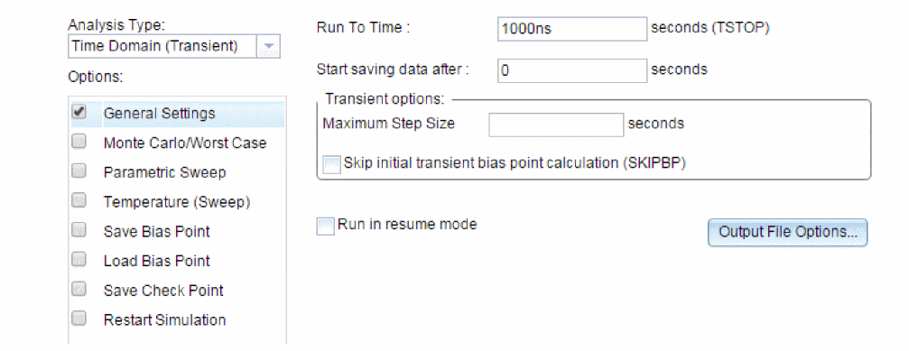
The Transient response analysis causes the response of the circuit to be calculated from TIME = 0 to a specified time. A transient analysis specification is shown for the circuit EXAMPLE.OPJ in Figure 12-1. (EXAMPLE.OPJ is shown in Figure 12-2.)
The analysis is to span the time interval from 0 to 1000 nanoseconds and values should be reported to the simulation output file every 20 nanoseconds.
Figure 12-1 Transient analysis setup for EXAMPLE.OPJ
During a transient analysis, any or all of the independent sources may have time-varying values. In EXAMPLE.OPJ, the only source which has a time-varying value is V1 (VSIN part) with attributes:
VOFF = 0v
VAMPL = 0.1v
FREQ = 5Meg
V1’s value varies as a 5 MHz sine wave with an offset voltage of 0 volts and a peak amplitude of 0.1 volts.
In general, more than one source has time-varying values for instance, two or more clocks in a digital circuit.
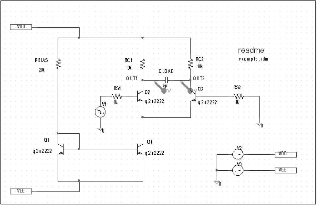
Figure 12-2 Example schematic EXAMPLE.OPJ.
The transient analysis does its own calculation of a bias point to start with, using the same technique as described for DC sweep. This is necessary because the initial values of the sources can be different from their DC values. In the simulation output file EXAMPLE.OUT, the bias point report for the transient bias point is labeled INITIAL TRANSIENT SOLUTION. To report the bias point information for nonlinear controlled sources and semiconductors, choose the OP option from the Output File Options dialog box. This bias point information is reported in the output file under the OPERATING POINT INFORMATION section.
Internal time steps in transient analyses
During analog analysis, PSpice A/D maintains an internal time step which is continuously adjusted to maintain accuracy while not performing unnecessary steps. During periods of inactivity, the internal time step is increased. During active regions, it is decreased. The maximum internal step size can be controlled by specifying it in the Maximum Time Step text box in the Transient dialog box. PSpice A/D will never exceed either the step ceiling value or two percent of the total transient run time, whichever is less.
The internal time steps used may not correspond to the time steps at which information is reported. The values at the print time steps are obtained by second-order polynomial interpolation from values at the internal steps.
When simulating mixed analog/ digital circuits, there are actually two time steps: one analog and one digital. This is necessary for efficiency. Since the analog and digital circuitry usually have very different time constants, any attempt to lock them together would greatly slow down the simulation. The time step shown on the PSpice A/D display during a transient analysis is that of the analog section.
Switching circuits in transient analyses
Running transient analysis on switching circuits can lead to long run times. PSpice A/D must keep the internal time step short compared to the switching period, but the circuit’s response extends over many switching cycles.
One method of avoiding this problem is to transform the switching circuit into an equivalent circuit without switching. The equivalent circuit represents a sort of quasi steady-state of the actual circuit and can correctly model the actual circuit’s response as long as the inputs do not change too fast.
This technique is described in: V. Bello, “Computer Program Adds SPICE to Switching-Regulator Analysis,” Electronic Design, March 5, 1981.
Plotting hysteresis curves
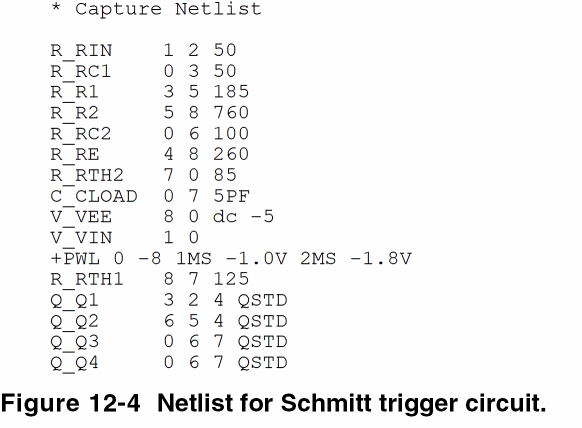
Transient analysis can be used to look at a circuit’s hysteresis. Consider, for instance, the circuit shown in Figure 12-3 (netlist in Figure 12-4).
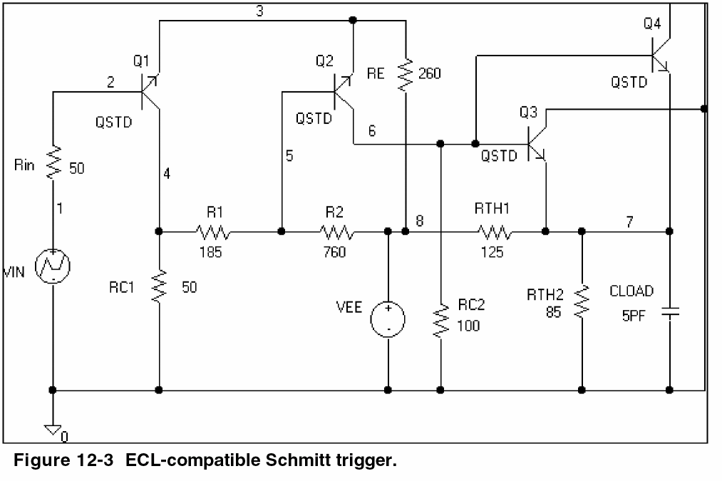
The QSTD model is defined as:
.MODEL QSTD NPN( is=1e-16 bf=50 br=0.1 rb=50 rc=10 tf=.12ns tr=5ns
+ cje=.4pF pe=.8 me=.4 cjc=.5pF pc=.8 mc=.333 ccs=1pF va=50)
Instead of using the DC sweep to look at the hysteresis, use the transient analysis, (Print Step = .01ms and Final Time = 2ms) sweeping VIN from -1.8 volts to -1.0 volts and back down to -1.8 volts, very slowly. This has two advantages:
- it avoids convergence problems
- it covers both the upward and downward transitions in one analysis
After the simulation, in the Probe window in PSpice A/D, the X axis variable is initially set to Time. By selecting X Axis Settings from the Plot menu and clicking on the Axis Variable button, you can set the X axis variable to V(1). Then use Add on the Trace menu to display V(7), and change the X axis to a user-defined data range from -1.8V to -1.0V (Axis Settings on the Plot menu). This plots the output of the Schmitt trigger against its input, which is the desired outcome. The result looks similar to Figure 12-5.
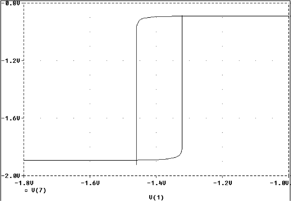
Figure 12-5 Hysteresis curve example: Schmitt trigger.
Fourier components
Fourier analysis is enabled through the Output File Options dialog box under the Time Domain (Transient) Analysis type. Fourier analysis calculates the DC and Fourier components of the result of a transient analysis. By default, the first through ninth components are computed however, more can be specified.
When selecting Fourier to run a harmonic decomposition analysis on a transient waveform, only a portion of the waveform is used. Using the Probe window in PSpice A/D, a Fast Fourier Transform (FFT) of the complete waveform can be calculated and its spectrum displayed.
In the example shown in Figure 12-1, the voltage waveform at node OUT2 from the transient analysis is used and the fundamental frequency is one megahertz for the harmonic decomposition. The period of fundamental frequency is one microsecond (inverse of the fundamental frequency). Only the last one microsecond of the transient analysis is used, and that portion is assumed to repeat indefinitely. Since V1’s sine wave does indeed repeat every one microsecond, this is sufficient. In general, however, you must make sure that the fundamental Fourier period fits the waveform in the transient analysis.
View the next document: 13 - Monte Carlo And Sensitivity (Worst-Case) Analyses
If you have any questions or comments about the OrCAD X platform, click on the link below.
Contact Us