04 - Creating And Editing PSpice Models
What are models? How are models organized? Tools to create and edit models Ways to create and edit models Ways to create and edit models Running the Model Editor alone Creating models using the Model Editor Model creation examples Editing model text Using the Create Subcircuit Format Netlist command Changing the model reference to an existing model definition Reusing instance models Configuring model libraries Handling smoke information using the Model Editor Examples: Smoke Smoke parameters
Chapter overview
This chapter provides information about creating and editing models for parts that you want to simulate.
Topics are grouped into four areas introduced later in this overview. If you want to find out quickly which tools to use to complete a given task and how to start, then:
- Go to the roadmap in Ways to create and edit models.
- Find the task you want to complete.
- Go to the sections referenced for that task for more information about how to proceed.
Background information
These sections present model library concepts and an overview of the tools that you can use to create and edit models:
Task roadmap
This section helps you find other sections in this chapter that are relevant to the model editing task that you want to complete:
How to use the tools
These sections explain how to use different tools to create and edit models on their own and when editing schematic pages or parts:
- For a list of device types that the Model Editor supports, see Table 4-2 and Table 4-3. If the Model Editor does not support the device type for the model definition that you want to create, then you can use a standard text editor to create a model definition using the PSpice A/D1 .MODEL and .SUBCKT command syntax. Remember to configure the new model library (see Configuring model libraries).
- Editing model text
- Using the Create Subcircuit Format Netlist command (Capture only)
Other useful information
These sections explain how to configure and reuse models after you have created or edited them:
- Changing the model reference to an existing model definition
- Reusing instance models
- Configuring model libraries
What are models?
A model defines the electrical behavior of a part. On a schematic page, this correspondence is defined by the Implementation property on the part, which is assigned the model name.
Depending on the device type that it describes, a model is defined as one of the following:
- a model parameter set
- a subcircuit netlist
Both ways of defining a model are text-based, with specific rules of syntax.
Models defined as model parameter sets
PSpice A/D has built-in algorithms or models that describe the behavior of many device types. The behavior of these built-in models is described by a set of model parameters.
You can define the behavior for a device that is based on a built-in model by setting all or any of the corresponding model parameters to new values using the PSpice .MODEL syntax. For example:
.MODEL MLOAD NMOS
+ (LEVEL=1 VTO=0.7 CJ=0.02pF)
Models defined as subcircuit netlists
For some devices, there are no PSpice built-in models that can describe their behavior fully. These types of devices are defined using the PSpice .SUBCKT/.ENDS or subcircuit syntax instead.
Subcircuit syntax includes:
- Netlists to describe the structure and function of the part.
- Variable input parameters to fine-tune the model.
For example:
* FIRST ORDER RC STAGE
.SUBCKT LIN/STG IN OUT AGND
+ PARAMS: C1VAL=1 C2VAL=1 R1VAL=1 R2VAL=1
+ GAIN=10000
C1 IN N1 {C1VAL}
C2 N1 OUT {C2VAL}
R1 IN N1 {R1VAL}
R2 N1 OUT {R2VAL}
EAMP1 OUT AGND VALUE={V(AGND,N1)*GAIN}
.ENDS
To find out more about PSpice A/D command and netlist syntax, refer to the PSpice A/D Reference Guide.
How are models organized?
The key concepts behind model organization are as follows:
- Model definitions are saved in files called model libraries.
- Model libraries must be configured so that PSpice A/D searches them for definitions.
- Depending on the configuration, model libraries are available either to a specific profile, to a specific design or to all (global) designs.
Model libraries
Device model and subcircuit definitions are organized into model libraries. Model libraries are text files that contain one or more model definitions. Typically, model library names have a .LIB extension.
Most model libraries contain models of similar type. For vendor-supplied models, libraries are also partitioned by manufacturer. For example, MOTOR_RF.LIB contains models for Motorola-made RF bipolar transistors.
To find out more about the models contained in a model library, read the comments in the file header.
Model library configuration
PSpice A/D searches model libraries for the model names specified by the MODEL implementation for parts in your design. These are the model definitions that PSpice A/D uses to simulate your circuit.
For PSpice A/D to locate these model definitions, you must configure the libraries. This means:
- Specifying the directory path or paths to the model libraries.
- Naming each model library that PSpice A/D should search and listing them in the desired search order.
- Assigning global, design or profile scope to the model library.
To optimize the model library search, PSpice A/D uses indexes. To find out more about this and how to add, delete, and rearrange configured libraries, see Configuring model libraries.
Global vs. design vs. profile models and libraries
Model libraries and the models they contain have either profile, design or global application to your designs.
Profile models
Profile models apply to one profile. You can create models using the Model Editor and then manually configure the new libraries for a specific profile.
Example usage: To set up device and lot tolerances on the model parameters for a particular part instance when running a Monte Carlo or sensitivity/ worst-case analysis using a specific profile.
Design models
Design models apply to one design. The schematic page editor automatically creates a design model whenever you modify the model definition for a part instance on your schematic page. You can also create models externally and then manually configure the new libraries for a specific design.
Example usage: To set up device and lot tolerances on the model parameters for a particular part instance when running a Monte Carlo or sensitivity/ worst-case analysis.
Global models
Global models are available to all designs you create. The part editor automatically creates a global model whenever you create a part with a new model definition. The Model Editor also creates global models. You can also create models externally and then manually configure the new libraries for use in all designs.
To find out how to change the profile, design and global configuration of model libraries, see Changing the model library scope from profile to design, profile to global, design to global and vice versa.
PSpice A/D searches profile libraries before design libraries and design libraries before global libraries. To find out more, see Changing model library search order.
Nested model libraries
Besides model and subcircuit definitions, model libraries can also contain references to other model libraries using the PSpice .LIB syntax. When searching model libraries for matches, PSpice A/D also scans these referenced libraries.
Example: Suppose you have two custom model libraries that you want PSpice A/D to search any time you simulate a design:
MYDIODES.LIB MYOPAMPS.LIB
Then you can create a third model library, MYMODELS.LIB, that contains these two statements:
.LIB mydiodes.lib
.LIB myopamps.lib
and configure MYMODELS.LIB for global use. Because MYDIODES.LIB and MYOPAMPS.LIB are referenced from MYMODELS.LIB, they are automatically configured for global use as well.
PSpice-provided models
The model libraries that you initially install with your PSpice A/D programs are listed in NOM.LIB. This file demonstrates how you can nest references to other libraries and models.
If you click the Configuration Files tab in the Simulation Settings dialog box and view the Library files list immediately after installation, you see the ![]()
NOM.LIB entry in the Library files list. The ![]() icon means that this model library and any of the model libraries it references contain global model definitions.
icon means that this model library and any of the model libraries it references contain global model definitions.
Model library data
Information contained in PSpice model libraries can be classified as:
- Simulation information
- Device information
Simulation information
Simulation information is also termed as model information and is used while simulating the models. Depending on the method of creation, PSpice simulation models are of two types:
- Device characteristic curves-based models
- Template-based models
Device characteristic curves-based models
Simulation models based on the device characteristic curves are the models that are historically being used in the PSpice A/D flow. You can extract device parameters based on the device characteristic curves in the data sheets.
Template-based models
These simulation models are based on PSpice-provided templates and are a new addition to the PSpice model library. Simulation models that are based on PSpice A/D provided templates are also referred to as parameterized models. Parameterized models are specified in terms of model parameters. Changing a parameter changes the behavior of the model. Template-based PSpice models describe the analog simulation behavior of a device in terms of parametric equations. These models are of the .SUBCKT type. The .SUBCKT wrapper enables symbol properties to be passed as parameters to the simulator.
The PSpice-provided templates are available in the TEMPLATES.LIB file. This is an encrypted file, and template-based models are wrappers to this file.
The main advantage of using template-based models is that simulation parameter values can be passed as properties from the design entry tool. Besides this, parameterized models are best suited to be used with PSpice Advanced Analysis, and also for performing statistical analysis for variations in model parameters.
Device information
Information that is specific to each device, such as simulation parameter tolerance and maximum operating conditions, is termed as device information. The device information is stored in the device property file and is required by PSpice Advanced Analysis. To know more about the device property file, see Appendix A, Property Files in the PSpice Advanced Analysis User Guide.
You can use the Model Editor to add device information to a model. For template-based simulation models, you can add smoke and tolerance information. For other simulation models, you can add only the smoke information.
Tolerance information is required to perform a Monte Carlo and Sensitivity/Worst-Case analysis. To know more about Monte Carlo and Sensitivity/Worst-Case analysis, see PSpice Advanced Analysis User Guide.
The tolerance information is added in the Simulation Parameters frame but smoke information can be added or modified only if you have Advanced Analysis installed.
Device characteristic curves-based models vs. Template-based models
| Device characteristic curves-based PSpice models | Template-based PSpice models |
|---|---|
|
They are based on device characteristic curves. Device characteristic curves can be obtained from device datasheets. |
They are based on PSpice-provided templates. |
|
They cannot be used for Advanced Analysis Sensitivity, Monte Carlo, and Optimizer runs. They can be used for Advanced Analysis smoke test only if smoke information is explicitly added. |
They can be used for all Advanced Analysis runs, such as Sensitivity, Smoke, Monte Carlo, and Optimizer. |
|
All simulation information is contained in the model itself. |
Models are wrappers to a template model file. Therefore, both the model and the template model are required for simulation. |
|
The PSpiceTemplate property must be attached to the symbol for generating the PSpice netlist. To know more about the PSpiceTemplate property, see PSPICETEMPLATE. |
The PSpiceTemplate property is not required on the symbol. The PORT_ORDER information present in the device property file is used for generating the PSpice netlist. The model library and the device property file must have the same name and must be at the same location.
To know more about the device property file, see Appendix A, Property Files in the PSpice Advanced Analysis User Guide. |
|
To modify a simulation property, you need to edit the simulation parameter. This implies that you either update the values in the original model or create an instance model for the design. To know more, see Using the Model Editor to edit the D1 diode model. |
Simulation parameter values can be passed as properties from the schematic editor. This implies that instance-specific values of simulation parameters can be passed from the schematic editor, without changing the original model. |
|
By default, tolerance and smoke information is not available in the models created using the Model Editor. Editing model text to add DEV and LOT information does not make the model compatible with Advanced Analysis Monte Carlo run. |
Tolerance and smoke information for the device is available in the device property file associated with the model library. If PSpice Advanced Analysis is installed, default values for the smoke parameters are visible through the Model Editor user interface. |
|
The shape and size of the part symbol generated by the Model Editor for the template-based models and device characteristic curves-based models may be different.
|
|
Tools to create and edit models
There are two tools that you can use to create and edit model definitions.
- The Model Editor
Use the Model Editor when you want to:- derive models from data sheet curves provided by manufacturers.
- create models based on PSpice-provided templates.
- modify the behavior of a Model Editor-supported model.
- edit the PSpice command syntax (text) for .MODEL and .SUBCKT definitions.
For template-based models, the model text is read-only and cannot be edited using the Model Editor.
- Capture
Use the Create Subcircuit Format Netlist command in Capture when you have a hierarchical level in your design that you want to set up as an equivalent part with behavior described as a subcircuit netlist (.SUBCKT syntax).
The Create Subcircuit Format Netlist command does not help you create a hierarchical design. You need to create this yourself before using the Create Subcircuit Format Netlist command. For information on hierarchical designs and how to create them, refer to the OrCAD X Capture User Guide.If you created a subcircuit definition using the Create Subcircuit Format Netlist command and want to alter it, use the Model Editor to edit the definition, or modify the original hierarchical schematic and run Create Subcircuit Format Netlist again to replace the definition.
Ways to create and edit models
This section is a roadmap to other information in this chapter. Find the task that you want to complete, then go to the referenced sections for more information.
| If you want to... | Then do this... | To find out more, see this... |
|---|---|---|
|
Start the Model Editor and enable/disable automatic symbol creation as needed. Then, create or view the model.
|
|
|
Copy the text of an existing model in a text editor and rename the file. or From the Model menu, choose the Copy From command. |
Model Editor Help |
|
First, create or load the symbol in the design entry tool, and then edit the model using the Model Editor. You can edit models by:
|
|
|
Start the Model Editor and open the library with the model, and then add the smoke information. This feature is available only if you have Advanced Analysis installed on your machine.
|
|
|
Select the part instance on your schematic and then edit the model text using the Model Editor. For template-based PSpice models, tolerance information can be added in the Postol and Negtol columns of the Simulation Parameters window.
|
|
|
Select the part instance on your schematic and then edit the model using either:
|
Running the Model Editor from the schematic editor.
|
|
In the Project Manager, select the .DSN file. From the Tools menu, choose Create Netlist, select the PSpice tab, and then check the Create Subcircuit Format Netlist check box. |
Using the Create Subcircuit Format Netlist command (Capture only). |
Using the Model Editor
The Model Editor converts information that you enter from the device manufacturer’s data sheet into either:
- model parameter sets using PSpice .MODEL syntax, or
- subcircuit netlists using PSpice .SUBCKT syntax.
The Extract Model view in the Model Editor does not support the following subcircuit constructs:- optional nodes construct, OPTIONAL:
- variable parameters construct, PARAMS:
- local .PARAM command
- local .FUNC command
To refine the subcircuit definition for these constructs, use the Model Text view in Model Editor, described in Editing model text.
The Model Editor then saves these definitions to model libraries that PSpice A/D can search when looking for simulation models.
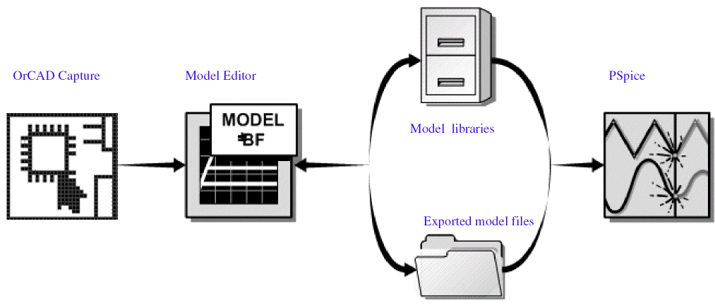
Figure 4-1 Relationship of the Model Editor to design entry tool and PSpice A/D.
Ways to use the Model Editor
You can use the Model Editor in the following ways:
- To define a new model, and then automatically create a part. Any new models and parts are automatically available to any design.
- To define a new model only (no part). You can optionally turn off the part creation feature for new models. The model definition is available to any design, for example, by changing the model implementation for a part instance.
- To edit a model definition for a part instance on your schematic. This means you need to start the Model Editor from the schematic editor after selecting a part instance on your schematic. The schematic editor automatically attaches the new model implementation (that the Model Editor creates) to the selected part instance. To find out more, see Running the Model Editor from the schematic editor.
- To examine or verify the electrical characteristics of a model without running PSpice A/D. This means you can use the Model Editor alone to:
- check characteristics of a model quickly, given a set of model parameter values, or
- compare characteristic curves to data sheet information or measured data.
To find out more, see Running the Model Editor alone . - To add and modify a model definition for parameterized or template-based PSpice models. This means you can create new parameterized models. You can also edit the existing models in the parameterized libraries to modify the values of simulation parameters.
- Adding and editing smoke data to the models supported by the Model Editor. If you have Advanced Analysis installed on your machine, you can use the Model Editor to add smoke information to device characteristic curves-based PSpice models. Editing of smoke information is possible for all types of PSpice models.
Running the Model Editor alone
Run the Model Editor alone if you want to do any of the following:
- create a model and use the model in any design (and automatically create a part),
- create a model and have the model definition available to any design (without creating a part), or
- examine or verify the characteristics of a given model without using PSpice A/D.
Running the Model Editor alone means that the model you are creating or examining is not currently tied to a part instance on your schematic page or to a part editing session.
Starting the Model Editor
To start the Model Editor alone
- From the Start menu, point to Programs, installed OrCAD X release, choose PSpice Accessories and then choose Model Editor.
- From the File menu, choose New or Open.
If you have already started the Model Editor from the design entry tool and want to continue working on new models, then:
- Save the opened model library.
- Open or create a different model library.
- Get a model, or create a new one.
Creating models using the Model Editor
Using the Model Editor, you can create models from scratch. The Model Editor supports creation of PSpice models based on device characteristic curves as well as templates. This section covers:
- Creating models based on device characteristic curves
- Creating models based on PSpice templates
Creating models based on device characteristic curves
- In the Model Editor, open a library.
- From the Models menu, choose New.
- Specify the name of the new model in the Model Name text box.
- Select the Use Device Characteristic Curves option.
- From the From Model drop-down list, select the device type and click OK.
Depending of the device type, you may have to provide some other details. For example, if the device type is Bipolar Transistor, you will also need to specify if the BJT will be of NPN or PNP type.All the device characteristic curves for the device and the simulation parameters are displayed. You can now characterize the models by either using data sheets or editing simulation parameter values.
Ways to characterize models
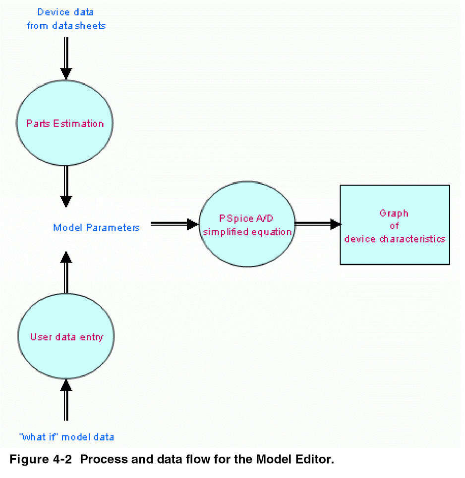
Figure 4-2 shows two ways to characterize PSpice models using the Model Editor.
Testing and verifying models created with the Model Editor
Each curve in the Model Editor is defined only by the parameters being adjusted. For the diode, the forward current curve only shows the part of the current equation that is associated with the forward characteristic parameters (such as IS, N, Rs).
However, PSpice A/D uses the full equation for the diode model, which includes a term involving the reverse characteristic parameters (such as ISR, NR). These parameters could have a significant effect at low current.
This means that the curve displayed in the Model Editor does not exactly match what is displayed in PSpice A/D after a simulation. Be sure to test and verify models using PSpice A/D. If needed, fine-tune the models.
Creating models from data sheet information
The most common way to characterize models is to enter data sheet information for each device characteristic. After you are satisfied with the behavior of each characteristic, you can have the Model Editor estimate (or extract) the corresponding model parameters and generate a graph showing the behavior of the characteristic. This is called the fitting process.
You can repeat this process, and when you are satisfied with the results, save them; the Model Editor creates model libraries containing appropriate model and subcircuit definitions.
Analyzing the effect of model parameters on device characteristics
You can also edit model parameters directly and see how changing their values affects a device characteristic. As you change model parameters, the Model Editor recalculates the behavior of the device characteristics and displays a new curve for each of the affected ones.
How to fit models
For a given model, the Model Editor displays a list of the device characteristics and a list of all model parameters and performance curves (see Figure 4-3).
For more information about the characteristics of devices supported by the Model Editor, refer to the PSpice A/D Reference Guide.
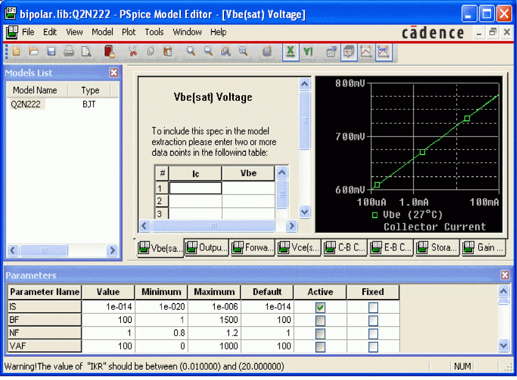
Figure 4-2 Model Editor workspace with data for a bipolar transistor.
To fit the model
- For each device characteristic that you want to set up:
- In the Spec Entry frame, click the tab of the device characteristic.
- Enter the device information from the data sheet.
- From the Tools menu, choose Extract Parameters to extract all relevant model parameters for the current specification.
A check mark appears in the Active column of the Parameters frame for each extracted model parameter. To keep a parameter value fixed, check the Fixed field corresponding to the parameter. - Repeat steps 1-2 until the model meets target behaviors.
To view updated performance curves
- On the toolbar, click the Update Graph button
 .
.
Model Editor-supported device types based on device characteristic curves
Device types that the Model Editor models using the .MODEL statement are based on the models built into PSpice A/D.
Table 4-2 summarizes the device types for which you can create PSpice models based on characteristic curves.
| This part type... | Uses this definition form... | And this name prefix... |
|---|---|---|
|
diode |
.MODEL |
D |
|
bipolar transistor |
.MODEL |
Q |
|
bipolar transistor, Darlington model |
.SUBCKT |
X |
|
IGBT |
.MODEL |
Z |
|
JFET |
.MODEL |
J |
|
MOSFET |
.MODEL |
M |
|
operational amplifier |
.SUBCKT |
X |
|
voltage comparator |
.SUBCKT |
X |
|
voltage regulator |
.SUBCKT |
X |
|
voltage reference |
.SUBCKT |
X |
|
magnetic core |
.MODEL |
K |
Creating models based on PSpice templates
An important advantage of using the template-based PSpice models is that you can pass simulation parameters as properties from the schematic editor. This implies that you can have instance-specific values for the model parameters.
For a description of template-based models supported by the Model Editor, see Model Editor-supported device types based on PSpice templates.
To create a template-based PSpice model, complete the following steps.
- In Model Editor, create a new library or open an existing library.
- From the Model menu, choose New.
- Specify the name of the new model in the Model Name text box.
- Select the Use Templates option.
- From the From Model drop-down list, select the device type.
Depending of the device type, you may have to provide some other details. For example, if the device type is Bipolar Transistor, you will also need to specify if the BJT will be of NPN or PNP type. - Click OK.
The Simulation parameters window appears with the default values of all simulation parameters. These values are editable and can be modified as required.
Notice that the Model Text window of a template-based PSpice model is not editable, it is read-only. Also, the model text does not display the port information under the .SUBCKT statement.
Adding tolerance information
While creating template-based simulation models, you can add tolerance information using the Model Editor user interface. Tolerance information is required only for Advanced Analysis Monte Carlo and Sensitivity runs and not for simulating the models.
The Postol, Negtol, and the Distribution columns are used to specify the tolerance information. In the Postol and Negtol columns, specify the positive and negative tolerances, respectively, for each of the simulation parameters. Adding a tolerance value enables the Distribution field for the parameter.
PSpice Advanced Analysis Monte Carlo uses original (nominal) parameter values to calculate results for each specification's first Monte Carlo run. For the subsequent Monte Carlo runs, Advanced Analysis uses distribution functions to randomly pick new parameter values within the manufacturer's tolerance.
The possible distribution types are:
- FLAT - Use the flat distribution function if you want an equal probability of one parameter value being chosen over another.
Use the flat distribution function if you want an equal probability that one parameter value will be chosen versus another. - BSIMD.4.2 - Use the bimodal distribution function if you want to represent the probability of a manufactured component falling in the outer range of tolerance values.
Use the bimodal distribution function if you want to represent the probability of a manufactured component failing in the outer range of tolerance values. For example, a resistor with a 10% tolerance might really only be available in the 5% to 10% range because the 1% to 4% resistors are picked out and sold as resistors with 5% tolerance. - GAUSS0.4 - Use the Gaussian distribution function if you want a bell curve probability that one parameter value will be chosen versus another.
Use the Gaussian distribution function if you want a bell curve probability that one parameter value will be chosen versus another. - SKEW.4.8 - Use the skewed distribution function if you want to weigh the probability of one parameter value being chosen versus another.
Use the skewed distribution function if you want to weigh the probability of one parameter value being chosen versus another.
Note:
By default, the distribution type is FLAT. The distribution type influences the Sensitivity and Monte Carlo analysis. To know more about Sensitivity and Monte Carlo analysis, see PSpice Advanced Analysis User Guide.
Model Editor-supported device types based on PSpice templates
Table 4-3 lists the device types for which template-based models can be created using the Model Editor.
| This part type... | And this name prefix... |
|---|---|
|
diode |
X |
|
bipolar transistor |
X |
|
IGBT |
X |
|
JFET |
X |
|
Power MOSFET |
X |
|
operational amplifier |
X |
|
voltage regulator |
X |
|
magnetic core |
K |
Importing an existing model
You can import third-party or vendor-provided Spice models into a format understood by the Model Editor. Importing a model enables editing the model using the Model Editor user interface.
- Open the Model Editor.
From the Start menu, point to installed OrCAD X release in the Programs folder, choose PSpice Accessories and then choose Model Editor. - Open a model library.
From the File menu, choose New or Open. - From the Model menu, choose Import.
- Select the file containing the model definition and select Open.
The imported model appears in the model library. Although, only the first model of the selected library file is imported to the Model Editor, it is recommended that the file selected in step 4 should contain only one model definition.
The device property file associated with the model is not imported.
Enabling and disabling automatic part creation
Part creation in the Model Editor is optional. By default, automatic part creation is enabled. However, if you previously disabled part creation, you will need to enable it before creating a new model and part.
Instead of using the PSpice A/D default part set for new models, you can have the Model Editor use your own set of standard parts.
To automatically create parts for new models
- From the Tools menu, choose Options.
- Select the Always Create Part when Saving Model option if it is not already checked.
- Under Schematic Editor, select the design entry tool name.
- Under Save Part To, enter the name of the part library for the new part. Choose either:
- Part Library Path Same As Model Library to create or open library file (*.olb) in Capture or a directory in Design Entry HDL that has the same name prefix as the currently open model library (* .lib ).
Example: In Capture, if the model library is MYPARTS.LIB, then the Model Editor creates the part library MYPARTS.OLB. Similarly, in Design Entry HDL, if the model library is MYPARTS.LIB, then the Model Editor creates a part directory with the name MYPARTS. - User-Defined Part Library, and then enter a file name in the Part Library Name text box.
- Part Library Path Same As Model Library to create or open library file (*.olb) in Capture or a directory in Design Entry HDL that has the same name prefix as the currently open model library (* .lib ).
Saving global models (and parts)
When you save your changes, the Model Editor does the following for you:
- In capture:
- Saves the model definition to the model library that you originally opened.
- If you had the automatic part creation option enabled, saves the part definition to model_library_name.OLB .
- In Design Entry HDL
- Saves the model definition to the model library that you originally opened.
- If you had the automatic part creation option enabled, saves the part definition to a
model_library_namedirectory that has subfolders for each part. In such cases the part name is same as the model name. - Creates a
cds.libfile. Thecds.libfile defines the location of the part directory created by the Model Editor.
If you want to save the open model library to a new library, then:
- From the File menu, choose Save As.
- Enter the name of the new model library.
If you want to save only the model definition that you are currently editing to a different library, then
- From the Model menu, select Export.
- Enter the name of the new file.
When you use the Export command, the model definition is saved with a.MODextension. You cannot export multiple models to a single MOD file. Exporting a model to the same file overwrites the original contents of the MOD file. - If you want PSpice A/D to search this file automatically, configure it in the design entry tool (using the Library files list in the Configuration Files tab on the Simulation Settings dialog box).
You cannot export multiple models to a single MOD file. Exporting a model to the same file overwrites the original contents of the MOD file.
To save the new model (and part)
- From the File menu, choose Save to update MODEL_LIBRARY_NAME.
LIB,MODEL_LIBRARY_NAME.PRP(and, if you enabled part creation, MODEL_LIBRARY_NAME directory), and save them to disk.
Running the Model Editor from the schematic editor
Start the Model Editor from the schematic editor when you want to:
- in Capture to define tolerances on model parameters for statistical analysis (see Example: editing a Q2N2222 instance model)
- test behavior variations on a part, or
- refine a model before making it available to all designs.
This means editing models for part instances on your schematic page. When you select a part instance and edit its model, the Model Editor automatically creates an instance model that you can then change.
Once you have started the Model Editor, you can proceed with entering data sheet information and model fitting as described in How to fit models.
You can also use the Model Editor to view the syntax for a model definition. When you have finished viewing, be sure to quit the Model Editor without saving the library, so that the schematic page editor does not create an instance model.
What is an instance model?
An instance model is a copy of the part’s original model. The copied model is local to the design. You can customize the instance model without impacting any other design that uses the original part from the library.
Instance models are created only when you want to edit models from global libraries. If you open a model for editing from a local library, after editing, the model will be saved in the same local library. For more information on global and local libraries see Global vs. design vs. profile models and libraries.
When the schematic editor creates the copy, it saves a copy of the model in design_name.LIB.
For more information on instance models, see Reusing instance models.
Starting the Model Editor
To start editing an instance model
- In the design entry tool, select one part on your schematic page.
- In Capture, choose Edit - PSpice Model. In Design Entry HDL, choose PSpice Simulator - Edit Model.
The schematic page editor searches the model libraries for the instance model. To find out how design entry tools searches the library, see Changing model library search order.- If found, the schematic page editor starts the Model Editor, which opens the design library and loads the instance model.
- If not found, the schematic page editor assumes that this is a new instance model and does the following: makes a copy of the original model definition in the DESIGN_NAME.LIB and starts the Model Editor with the new model loaded.
Saving design models
When you save your edits, the following is done for you to make sure the instance model is linked to the selected part instances in your design:
- The Model Editor saves the model definition to DESIGN_NAME.
LIB. - If the library is new, the Model Editor configures DESIGN_NAME.
LIBfor local use.
The schematic page editor assigns the new model name to the Implementation property for each of the selected part instances (see What happens if you do not save the instance model).
To save instance models
- From the File menu, choose Save to update DESIGN_NAME.LIB and save it to disk.
Actions that automatically configure the instance model library for global use
Instance model libraries are normally configured for design use. However, if you perform the following action, the Model Editor configures the library for global use instead:
- Save the model to a different library by typing a new file name in the Library text box in the Save To frame.
To save instance models
- From the File menu, choose Save to update DESIGN_NAME.LIB and save it to disk.
What happens if you do not save the instance model
Before the schematic page editor starts the Model Editor, it does the following:
- Makes a copy of the original model and saves it as an instance model in SCHEMATIC_NAME.LIB.
- Configures SCHEMATIC_NAME.LIB for design use, if not already done.
- Attaches the new instance model name to the Implementation property for the selected part instance.
This means that if you:
- quit the Model Editor, or
- return to the design entry tool to simulate the design
without first saving the model you are editing, the part instance on your schematic page is still attached to the instance model implementation.
In this case, the instance model is identical to the original model. If you decide to edit this model later, be sure to do one of the following:
- If you want the changes to remain specific to the current design, edit the instance model in the design library using the Model Editor.
- If you want the change to be global, change the model implementation for the part instance in your design back to the original model name in the global library, and then edit the original model from within the part editor.
To find out how to change model references, see Changing the model reference to an existing model definition.
Model creation examples
Examples covered in this section cover how to use the Model Editor to create simulation models based on:
- Device characteristic curves. See Example: Creating a PSpice model based on device characteristic curves.
- PSpice-provided templates. See Example: Creating template-based PSpice model.
Example: Creating a PSpice model based on device characteristic curves
In this example, you will model a simple diode device as follows:
- Create the schematic for a simple half-wave rectifier.
- Create a new model for a diode.
- Attach new model to the D1 diode.
Creating the half-wave rectifier design
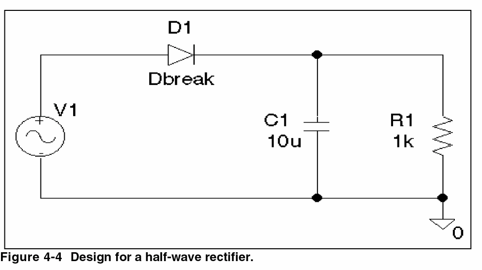
To create the design in Capture
- From the Project Manager, from the File menu point to New, then choose Project.
- In the New Project dialog box, ensure that the Analog or Mixed A/D option is selected.
- Enter the name of the new project (RECTFR) and click Create.
- From the Capture Place menu, choose Part.
- Place one each of the following parts (reference designator shown in parentheses) as shown in Figure 4-4:
- Dbreak (D1 diode)
- C (C1 capacitor)
- R (R1 resistor)
- VSIN (V1 sine wave source)
- Click the Ground button
 on the tool palette and place the ‘0’ analog ground from the SOURCE.OLB part library.
 - From the Place menu, choose Wire, and draw the connections between parts as shown in Figure 4-4.
- From the File menu, choose Save.
- Invoke Project Manager.
- In Project Manager, from the File menu, choose New. The New Project Wizard appears.
- In the Name text box, enter the name of the project (
RECTFR). - In the Location text box, enter the path to the directory where you want to create the project
- Click Next. The Project Libraries dialog box appears.
- Select
analogfrom the list of Available Libraries, and click Add. Theanaloglibrary is added to the Project Libraries list. - Add the following libraries as described in step 14 above:
BREAKOUTsource
- Click Next. The Design Name dialog box appears.
- In the Design Name text box, enter the name of the top level design (
RECTFR). - Click Next. The Summary dialog box displays the project details.
- Click Finish to create the project.
To create the design in Design Entry HDL
Create a new design project:
- Invoke Project Manager.
- In Project Manager, choose File – New. The New Project Wizard appears.
- In the Name text box, enter the name of the project (
RECTFR). - In the Location text box, enter the path to the directory where you want to create the project
- Click Next. The Project Libraries dialog box appears.
- Select
analogfrom the list of Available Libraries, and click Add. Theanaloglibrary is added to the Project Libraries list. - Add the following libraries as described in step 14 above:
BREAKOUTsource
- Click Next. The Design Name dialog box appears.
- In the Design Name text box, enter the name of the top level design (
RECTFR). - Click Next. The Summary dialog box displays the project details.
- Click Finish to create the project.
To create the design, invoke the Design Entry HDL schematic editor.
- In Project Manager, click on the Design Entry icon. Design Entry HDL appears.
- From the Component menu, choose Add. The Component Browser appears.
- Place one each of the following parts (reference designator shown in parentheses) as shown in Figure 4-5:
- Dbreak (D1 diode) from the BREAKOUT library
- C (C1 capacitor) from the ANALOG library
- R (R1 resistor) from the ANALOG library
- VSIN (V1 sine wave source) from the SOURCE library
- 0 analog ground from the SOURCE library.
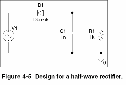
- From the Wire menu, choose Draw and draw the connections between parts as shown in Figure 4-5.
- From the File menu, choose Save.
Using the Model Editor to edit the D1 diode model
To create a new model and model library
- Open the Model Editor.
- From the File menu in the Model Editor, choose New.
- From the Model menu, choose New.
- In the New dialog box, do the following:
- In the Model Name text box, type
DbreakX. - Select Use Device Characteristic Curves.
- From the From Model list, select Diode.
- Click OK.
- In the Model Name text box, type
- From the File menu, choose Save.
By default, the updated model is saved in theRECTFR.LIBlibrary.
Entering data sheet information
As shown in Figure 4-6, the Model Editor initially displays:
- diode model characteristics listed in the Models List window, and
- DbreakX model parameter values listed in the Parameters window.
Figure 4-6 Model characteristics and parameter values for DbreakX.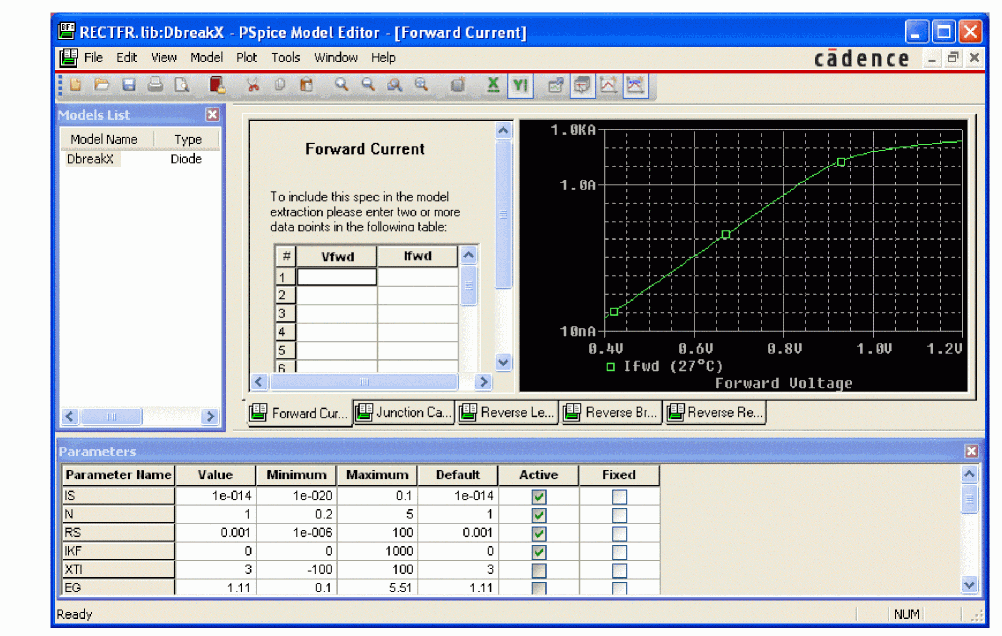
You can modify each model characteristic shown in the Model Spec frame with new values from data sheets. The Model Editor takes the new information and fits new model parameter values.
When updating the entered data, the Model Editor expects either:
- device curve data (point pairs) or
- single-valued data
depending on the device characteristic.
For the diode, Forward Current, Junction Capacitance, and Reverse Leakage require device curve data. Reverse Breakdown and Reverse Recovery require single-valued data.
Table 4-4 lists the data sheet information for the DbreakX model.
| For this model characteristic... | Enter this... |
|---|---|
|
forward current |
(1.3, 0.2) |
|
junction capacitance |
(1m, 120p) (1, 73p) (3.75, 45p) |
|
reverse leakage |
(6, 20n) |
|
reverse breakdown |
(Vz=7.5, Iz=20m, Zz=5) |
|
reverse recovery |
no changes |
To change the Forward Current characteristic
- In the Spec Entry frame, click the Forward Current tab.
This tab requires curve data. - In the Vfwd text box, type
1.3. - Press Tab to move to the Ifwd text box, and then type
0.2.
To change the values for Junction Capacitance and Reverse Leakage
Follow the same steps as for Forward Current, entering the data sheet information listed in Table 4-4 that corresponds to the current model characteristic.
To change the Reverse Breakdown characteristic
- In the Spec Editing frame, click the Reverse Breakdown tab.
This tab requires single-valued data. - In the Vz text box, type
7.5.
The Model Editor accepts the same scale factors normally accepted by PSpice A/D. - Press Tab to move to the Iz text box, and then type
20m. - Press Tab to move to the Zz text box, and then type
5.
Extracting model parameters
To generate new model parameter values
- From the Tools menu, choose Extract Parameters.
A check mark appears in the Active column of the Parameters frame for each extracted model parameter.
To display the curves for the five diode characteristics
- From the Window menu, choose Tile.
Some of the plots are shown in Figure 4-7 below.
Figure 4-7 Assorted device characteristic curves for a diode.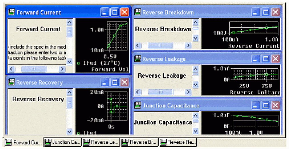
You can also do the following with an active plot window:
- Pan and zoom within the plot using commands on the View menu.
- Rescale axes using the Axis Settings command on the Plot menu.
Adding curves for more than one temperature
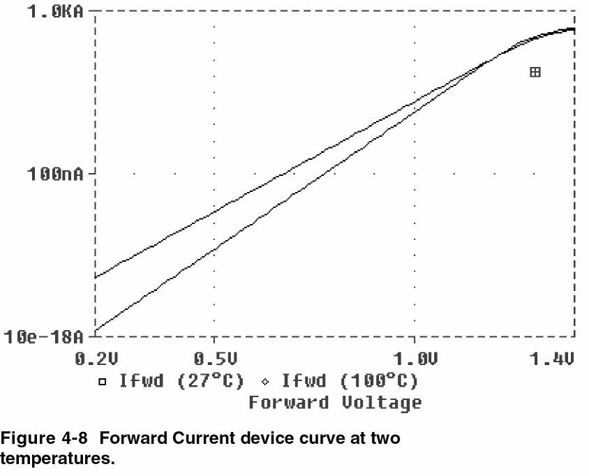
By default, the Model Editor computes device curves at 27°C. For any characteristic, you can add curves to the plot at other temperatures.
To add curves for Forward Current at a different temperature
- In the Spec Entry frame, click the Forward Current tab.
- From the Plot menu, choose Add Trace.
- Type
100(in °C). - Click OK.
The Forward Current plot should appear as shown in Figure 4-8.
Completing the model definition
You can refine the model definition by:
- modifying the entered data as described before, or
- editing model parameters directly.
You can update individual model parameters by editing them in the Parameters frame of the Model Editor workspace. When you save the model library, the Model Editor automatically updates the device curves.
For this tutorial, leave the model parameters at their current settings.
To save the model definition with the current parameter values and to make the model available to your design
- From the File menu, select Save to update
RECTFR.LIBand save the library to disk.
The model definition is now complete. You can use this model definition in your design.
Attaching the DbreakX model to the D1 diode in Capture
- In Capture, open the RECTFR project.
- Select the D1 diode.
- From the Edit menu, choose Properties.
- In the Property Editor dialog box, change the value of Implementation property from Dbreak to DbreakX.
To know more about the Implementation property. - Close the dialog box, and save the design.
Your design is ready to simulate with the model definition you just created.
Example: Creating template-based PSpice model
In this example, you will create a template-based PSpice model for an operational amplifier, using the Model Editor.
The template-based OPAMP model is the only model created using the Model Editor that has multiple level support for simulation parameters. Tasks that will be covered in this example are:
- Creating a new template-based PSpice model for Operational Amplifier
- Multiple level support for template-based OPAMP models in the Model Editor
Multiple level support implies that the number of simulation parameters used in the model varies with the model level. The higher the level, the more are the number of simulation parameters.
The models with a higher number of simulation parameters are closer to the real life devices. Therefore, the simulation results are more accurate when high level models are used. Use lower level simulation models to minimize the simulation time.
Creating a new model
- Start the Model Editor alone.
- From the File menu, choose New to create a new library.
- From the Model menu, choose New.
- In the New dialog box, specify the name of the new model as
OPA_LOCAL. - Select the Use Templates option.
- To specify the device type, select Operational Amplifier from the From Model drop-down list.
- Specify the type of OPAMP to be created. In this example, select options to create an internally compensated bipolar operational amplifier with PNP input.
Figure 4-9 The New dialog box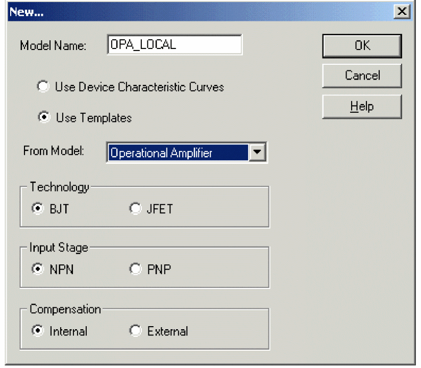
- Click OK.
The Simulation Parameters and the Model Text windows appear. In the Models List, three models,OPA_LOCAL_1,OPA_LOCAL_2, andOPA_LOCAL_3appear.
The Model Editor creates multiple models only for Advanced Analysis OPAMP models. This is because, template-based OPAMP models support multiple levels of simulation parameters, and the Model Editor creates one model for each level.
TheOPA_LOCAL_3model contains all the simulation parameters available in theOPA_LOCAL_2model plus some extra simulation parameters. TheOPA_LOCAL_2model contains some additional simulation parameters besides the ones listed in theOPA_LOCAL_1model. - Select the
OPA_LOCAL_3model, and edit the values of the simulation parameters listed in Table 4-5. Table 4-5 lists the simulation parameters along with the new values. For other simulation parameters not listed in the table, accept the default values.
Table 4-5 List of Simulation Parameters to be modified
Simulation Property Name Value Distribution Postive Tolerance (Postol) Negative Tolerance (Negtol) VOS
1e-7
FLAT
10%
10%
IB
default
FLAT
10%
10%
IBOS
default
FLAT
10%
10%
A0
1000000
FLAT
10%
10%
GBW
default
FLAT
10%
10%
SRP
1.0e+6
FLAT
10%
10%
SRM
1.0e+6
FLAT
10%
10%
CMRR
default
FLAT
10%
10%
- To ensure that the values entered by you in the Simulation Parameters frame overwrite the default value of the simulation parameters, check the Editable check box for all the simulation properties.
Selecting the Editable check box ensures that the simulation parameter value:- entered by users will overwrite the values in the template property file.
- appears in the device property file.
- can be directly passed from the schematic editor as properties attached to the symbol.
In such cases, the values of the simulation parameters can be picked up from following three locations in the decreasing order of priority:- schematic editor
- device property file
- template property file
- After making the simulation parameters editable, save the model. Specify the library name as LOCAL_LIB.
All the changes in theOPA_LOCAL_3model are reflected in theOPA_LOCAL_2andOPA_LOCAL_1models also. This is because all three models have a common section for the simulation and smoke parameters in the device property file,LOCAL_LIB.PRP.
It is recommended that multiple level models created using the Model Editor should be used cautiously especially when used in different designs.
Consider a situation where you useOPA_LOCAL_1from theLOCAL_LIBlibrary in design A andOPA_LOCAL_3from theLOCAL_LIBlibrary in design B. Any changes that you make to the simulation or smoke parameter values of theOPA_LOCAL_1model for design A will also be reflected in theOPA_LOCAL_3model used in design B.
After you have saved your changes in the Model Editor, the following files are generated:
LOCAL_LIB.LIB- The library file containing model information.LOCAL_LIB.PRP- The device property file containing device specific information for all the models in theLOCAL_LIB.LIB.
Saving the LOCAL_LIB library completes the tasks of creating a template-based PSpice model for Operational Amplifier. Because of the multiple-level support for Advanced Analysis OPAMP models in the Model Editor, instead of one, three models are created.
Editing model text
The Model Text is editable only for PSpice models. For template-based PSpice models, the Model Text window is read-only.
For any model, you can edit model text in the Model Editor instead of using the Spec Entry and Parameter frames. However, there are two cases where you must edit the model text:
- When you want to edit models of device types not supported by the Model Editor. The model text is displayed automatically when you load one of these models.
- When you want to add DEV and LOT tolerances for Monte Carlo or sensitivity/worst-case analysis.
By typing PSpice commands and netlist entries, you can do the following:
- change definitions, and
- create new definitions
When you have finished, the Model Editor automatically configures the model definitions into the model libraries.
To display the model text
- From the View menu, choose Edit Model.
The Model Editor displays the PSpice syntax for model definitions:- .MODEL syntax for models defined as parameter sets
- .SUBCKT syntax for models defined as netlist subcircuits
To find out more about PSpice command and netlist syntax, refer to the PSpice A/D Reference Guide.
Editing .MODEL definitions
For definitions implemented as model parameter sets using the PSpice .MODEL syntax, the Model Editor lists one parameter per line. This makes it easier to add DEV/LOT tolerances to model parameters for Monte Carlo or sensitivity/worst-case analysis.
Editing .SUBCKT definitions
For definitions implemented as subcircuit netlists using the PSpice .SUBCKT syntax, the Model Editor displays the subcircuit syntax exactly as it appears in the model library. The Model Editor also includes all of the comments immediately before or after the subcircuit definition.
Changing the model name
You can change the model name directly in the PSpice .MODEL or .SUBCKT syntax, but double-check that the new name does not conflict with models already contained in the libraries. To find out more about instance model naming conventions, see What is an instance model?.
Example: editing a Q2N2222 instance model
Suppose you have a design named MY.OPJ that contains several instances of a Q2N2222 bipolar transistor. If you want to see the effect of base resistance variation on one specific device, Q6, you need to do the following:
- Define a tolerance (in this example, 5%) on the Rb model parameter.
Adding tolerance to a device characteristic curve-based model does not make it compatible for use with Advanced Analysis Monte Carlo. - Set up and run PSpice Monte Carlo analysis.
The following example demonstrates how to set up the instance model for Q6.
Starting the Model Editor
To start the Model Editor,
- In the schematic page editor, select Q6 on the schematic page.
- From the Edit menu, choose PSpice Model.
The Model Editor automatically creates a copy of the Q2N2222 base model definition. - In the Model Editor, from the View menu, choose Model Text.
The Model Editor displays the PSpice syntax for the copied model in the text editing area.
Editing the Q2N2222 model instance
Text edits appropriate to this example are as follows:
- Add the
DEV 5%clause to theRbstatement (required). - Change the model name to
Q2N2222-MC(optional, for descriptive purposes only).
To find out more about PSpice command and netlist syntax, refer to the PSpice A/D Reference Guide.
Saving the edits and updating the schematic
When you choose Save from the File menu, two things happen:
- The Model Editor saves the model definition to the model library.
- The schematic page editor updates the Implementation property value to Q2N2222-MC for the Q6 part instance.
In this example, the default model library is MY.LIB. If MY.LIB does not already exist, the Model Editor creates and saves it in the current working directory. The schematic page editor then automatically configures it as a design model library for use with the current design only.
Now you are ready to set up and run the Monte Carlo analysis.
Using the Create Subcircuit Format Netlist command (Capture only)
The Create Subcircuit Format Netlist command is used from Capture. This command creates a subcircuit netlist definition for the displayed level of hierarchy and all lower levels in your design.
The schematic page editor does the following things for you:
- Maps any named interface ports at the active level of hierarchy to terminal nodes in the PSpice .SUBCKT statement.
- Saves the subcircuit definition to a file named DESIGN_NAME-SCHEMATIC_NAME.LIB.
Before you can use the subcircuit definition in your design, you need to:
- Create a part for the subcircuit.
- Configure the DESIGN_NAME-SCHEMATIC_NAME.LIB file so PSpice A/D knows where to find it.
To create a subcircuit definition for a portion of your design
To create a subcircuit netlist definition
- In the Project Manager, select the schematic folder that contains the circuitry for which a subcircuit netlist definition is to be created.
- If the schematic folder is not the root folder, choose Make Root from the Design menu. You may be prompted to save the design first.
- In the Project Manager, from the Tools menu, choose Create Netlist.
- Select the PSpice tab.
- In the Options frame, select Create SubCircuit Format Netlist.
- Click OK to generate the subcircuit definition and save it to DESIGN_NAME-SCHEMATIC_NAME.LIB.
To create a part for the subcircuit netlist definition
- Open the Model Editor alone.
- From the File menu, select the Open command and open the DESIGN_NAME-SCHEMATIC_NAME.LIB file.
- Select the model from the Models List and, if necessary, refine the subcircuit definition.
Refinements can include extending the subcircuit definition using the optional nodes construct, OPTIONAL:, the variable parameters construct, PARAMS:, and the .FUNC and local .PARAM commands. - From the File menu, select Create Capture Parts.
- In the Enter Input Model Library text box, browse and open the DESIGN_NAME-SCHEMATIC_NAME.LIB file.
The Enter Output Part Library is automatically filled in with the DESIGN_NAME-SCHEMATIC_NAME.OLB file. - Click OK and OK again to clear the .ERR log window.
The subcircuit part is now ready for use in a design.
To configure the subcircuit file
- In the schematic page editor, from the PSpice menu, choose Edit Profile to display the Simulation Settings dialog box.
- Click the Configuration Files tab.
- Click either Library or Include in the Category field of the Configuration Files tab, and then configure DESIGN_NAME-SCHEMATIC_NAME.LIB as either a model library or an include file (see Configuring model libraries).
Changing the model reference to an existing model definition
Parts are linked to models by the model name assigned to the parts’ Implementation property. You can change this assignment by replacing the Implementation property value with the name of a different model that already exists in the library.
You can do this for:
- A part instance in your design.
- A part in the part library.
To change model references for part instances on your design
- Find the name of the model that you want to use.
- In the schematic page editor, select one or more parts on your schematic page.
- From the Edit menu, choose Properties.
The Parts spreadsheet appears. - Click the cell under the column Implementation Type.
- From the Implementation list, select PSpice Model.
- In the Implementation column, type the name of the existing model that you want to use if it is not already listed.
- Click Apply to update the changes, then close the spreadsheet.
To change the model reference for a part in the part library
- Find the name of the model that you want to use.
- In the schematic page editor, select the part you want to change.
- From the Edit menu, choose Part to load the part in the part editor for editing.
- From the Options menu, choose Part Properties to display the User Properties dialog box.
- Select Implementation Type.
- From the Implementation list, select PSpice Model.
- In the Implementation text box, type the name of the existing model that you want to use if it is not already listed.
- Click OK to close the Edit Part dialog box.
Reusing instance models
If you created instance models in your design and want to reuse them, there are two things you can do:
- Attach the instance model implementation to other part instances in the same design.
- Change the instance model to a global model and create a part that corresponds to it.
For information on how to create instance models, see:
Reusing instance models in the same schematic
There are two ways to use the instance model elsewhere in the same design.
To use the instance model elsewhere in your design
Do one of the following:
- Change the model reference for other part instances to the name of the new model instance.
See Changing the model reference to an existing model definition. - From the Edit menu, use the Copy and Paste commands to place more part instances.
Making instance models available to all designs
If you are refining model behavior specific to your design, and are ready to make it available to any design, then you need to link the model definition to a part and configure it for global use.
To make your instance model available to any design
- Create a part and assign the instance model name to the Implementation property. See Chapter 5, “Creating parts for models” for more information.
- If needed, move the instance model definition to an appropriate model library, and make sure the library is configured for global use. See Configuring model libraries for more information.
Configuring model libraries
Although model libraries are usually configured for you, there are things that you sometimes must do yourself. These are:
- adding new model libraries that were created outside of the design entry tools or the Model Editor
- changing the global, design or profile scope of a model library
- changing the library search order
- changing or adding directory search paths
The Configuration Files tab
The Configuration Files tab of the Simulation Settings dialog box lets you add, change, and remove model libraries and include files from the configuration or modify the search order.
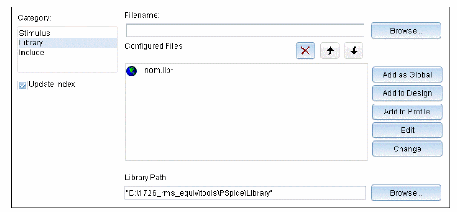
To display the Library files list
- In PSpice A/D, open or create a PSpice project.
- From the PSpice menu, choose either New Simulation Profile or Edit Profile if a profile already exists.
- Click the Configuration Files tab in the Simulation Settings dialog box.
- Click Library in the Category field to display the Library files list.
The Library files list shows the model libraries that PSpice A/D searches for definitions matching the parts in your design. Files showing an icon after their name have global scope; files having the
  icon have a design scope and files with the
  icon have a profile scope.
The buttons for adding model libraries to the configuration follow the same profile/local/global syntax convention. Click one of the following:- Add to Profile for profile models
- Add to Design for design models
- Add as Global for global models
-
- Profile or Global level creates a copy of the model under the simulation folder and the project folder respectively. Changes made to the model are saved in the copied model.
- Design level points to the original model. Changes made to the model are saved in the original model itself.
The Include files list in the Configuration Files tab contains include files. You can manually add profile, design and global include files to your configuration using the Add to Profile, Add to Design and Add as Global buttons, respectively.
The Stimulus files list in the Configuration Files tab contains stimulus files.
How PSpice A/D uses model libraries
PSpice A/D searches libraries for any information it needs to complete the definition of a part or to run a simulation. If an up-to-date index does not already exist, PSpice A/D automatically generates an index file and uses the index to access only the model definitions relevant to the simulation. This means:
- Disk space is not used up with definitions that your design does not use.
- There is no memory penalty for having large model libraries.
- Loading time is kept to a minimum.
If you refer to a library file from a location where you do not have write permissions, PSpice A/D might not be able to open or make an index file. To resolve this create a.libfile at a location you have permissions and include the original file in this.libfile, then add this file to the Configuration Files tab of the Simulation Settings dialog box. For example, if you use a fileoriginal.liblocated at\\server\Cadence\liband do not have permissions on\\server\Cadence\lib:- Create a file, say
my.lib, at a location where you have permission - Edit
my.libto include the line:.lib \\server\Cadence\lib\original.lib - Add the location of
my.libin the Configuration Files tab of Simulation Settings dialog box.
- Create a file, say
Caution—When you use include files instead
PSpice A/D treats model library and include files differently as follows:
- For model library files, PSpice A/D reads in only the definitions it needs to run the current simulation.
- For include files, PSpice A/D reads in the file in its entirety.
This implies that if you configure a model library (*.LIB extension) as an include file using the Add to Design or Add as Global button, PSpice A/D loads every model definition contained in that file.
If the model library is large, you might overload the memory capacity of your system. However, when developing models, you can do the following:
- Initially configure the model library as an include file; this avoids rebuilding the index files every time the model library changes.
- When your models are stable, reconfigure the include file containing the model definitions as a library file.
To reconfigure an include file as a model library file:
- From the Simulation menu, choose Edit Profile, then click the Configuration Files tab.
- Click Include in the Category field to display the Include files list.
- Select the include file that you want to change.
- Click the Delete button located above the Include files list.
See Adding model libraries to the configuration.
Search order
When searching for model definitions, PSpice A/D scans the model libraries using these criteria:
- profile model libraries before design model libraries
- design model libraries before global model libraries
- model library sequence as listed in the Library files list in the Configuration Files tab of the Simulation Settings dialog box
- list of directories (including the design library) specified in the library search path in the order given (see Changing the library search path). From the directories listed in the Library Path, only the directories that contain a
NOM.LIBfile are looked up by PSpice A/D during the model search.
The search order for the device property files is same as that of the model library files. The .PRP files are searched along with the .LIB files.
Handling duplicate model names
If two or more model libraries contain models with the same name, PSpice A/D always uses the first model it finds. This means you might need to modify the search order to make sure PSpice A/D uses the model that you want. See Changing model library search order.
Adding model libraries to the configuration
New libraries are added above the selected library name in the Library files list box.
To add model libraries to the configuration
- From the Simulation menu, choose Edit Profile, then click the Configuration Files tab.
- Click Library in the Category field to display the Library files list.
- Click the library name positioned one entry below where you want to add the new library.
- In the Filename text box, either:
- type the name of the model library, or
- click Browse to locate and select the library.
- Do one of the following:
- If the model definitions are for use in the current profile only, click the Add to Profile button.
- If the model definitions are for use in the current design only, click the Add to Design button.
- If the model definitions are for global use in any schematic, click the Add as Global button instead.
- Click OK.
Changing the model library scope from profile to design, profile to global, design to global and vice versa
There are times when you might need to change the scope of a model library from profile to design, profile to global, design to global, or vice versa.
Example: If you have an instance model that you now want to make available to any design, then you need to set the scope of the local model library that contains it to global.
For more information, see Global vs. design vs. profile models and libraries.
To change the scope of a design model to global
- From the Simulation menu, choose Edit Profile, then click the Configuration Files tab.
- Click Library in the Category field to display the Library files list.
- Select the model library that you want to change.
- Click the Delete toolbar button to remove the local entry.
- Add the model library as a global entry.
For more information, see Adding model libraries to the configuration.
Changing model library search order
Two reasons why you might want to change the search order are to:
- reduce the search time
- avoid using the wrong model when there are model names duplicated across libraries. PSpice A/D always uses the first instance. See Handling duplicate model names for more information.
To change the order of libraries
- Click the Configuration Files tab in the Simulation Settings dialog box.
- Click Library in the Category field to display the Library files list. On the Library files list of the Configuration Files tab:
- Select the library name you wish to move.
- Use either the Up Arrow or Down Arrow toolbar button to move the library name to a different place in the list.
You can only change the order of libraries that have the same scope. This implies that though you can change the order of profile libraries, local libraries and global libraries, you cannot place a global library before a local library or a local library before a profile library.
- If you have listed multiple *
.LIBcommands within a single library (likeNOM.LIB), then edit the library using a text editor to change the order.
Example: The model librariesDIODES.LIBandEDIODES.LIB(European manufactured diodes) shipped with your PSpice A/D programs have identically named device definitions. If your design uses a device out of one of these libraries, you need to position the model library containing the definition of choice earlier in the list. If your system is configured as originally shipped, this means you need to add the specific library to the list beforeNOM.LIB.
Do not edit NOM.LIB. If you do, PSpice A/D will recreate the indexes for every model library referenced in NOM.LIB. This can take some time. - After you have modified the library settings using the Simulation Settings dialog box, you must first select the design name in the Project Manager and then save the design by clicking the save button. This must be done every time you make a change in the Simulation Settings dialog box. This is to ensure that the changes in the simulation settings are reflected in the
.OPJfile and are picked up the netlister in the subsequent flows.
Order of Access and Precedence for Models used in Simulation
You can configure model libraries at simulation profile level, design-level, and custom-global-level (using the Simulation Setting dialog box).
Order of Access
You can access the models that are used for simulation in the following order:
- Models from libraries added to profile
- Models from libraries added to design
- Models from globally configured libraries
Order of Precedence
In the Simulation Settings dialog box, by selecting the check box Prioritize models for same .lib for all circuits, you can follow a particular order of precedence in the design.
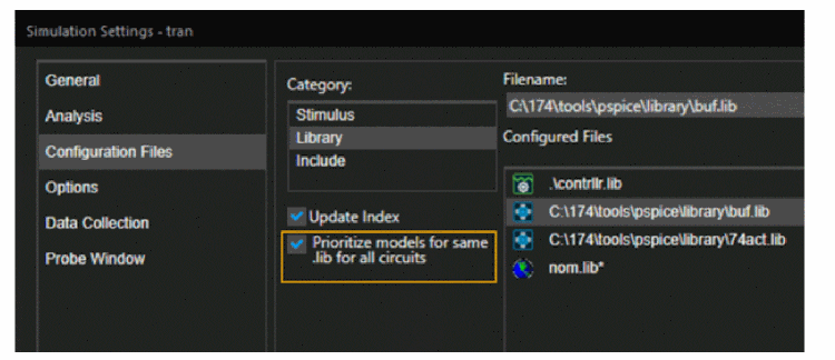
If you select this check box, the following precedence for models takes place:
- Models referred directly on schematic or design: If there is a model with multiple definitions in the configured libraries, then models are accessed as per the order explained above.
- Model referred by a subcircuit model definition: For the models that are referred to from a specific subcircuit model definition, highest precedence is assigned to the model definition found in same library file. If models or subcircuits are not found in the current library, then they are searched from other libraries as per the order of access explained above.
Example
If a subcircuit, TOP_B in a library file LIBRARY_B refers to another model/subcircuit, then this model/subcircuit will first be searched in the current library where TOP_B is defined, that is LIBRARY_B.
On a schematic, if you have placed the following parts:
- Subcircuit,
TOP_B- Which refers to subcircuit,
SUB_TOP_B- Where
SUB_TOP_Brefers to model,MOSFET_M
- Where
- Which refers to subcircuit,
- Model,
DIODE_M
The order in which libraries are indexed is as follows:
LIBRARY_A, has the following definition:SUB_TOP_B(subcircuit)DIODE_M(model)MOSFET_M(model)
LIBRARY_B, which has the following definition:TOP_B(subcircuit)SUB_TOP_B(subcircuit)DIODE_M(model)
Now on simulation, the models are picked in the following manner:
TOP_Bgets picked fromLIBRARY_BSUB_TOP_Bgets picked fromLIBRARY_BMOSFET_Mgets picked fromLIBRARY_A
DIODE_Mgets picked fromLIBRARY_A
The same behavior is applicable for parameter statements defined in the library file as shown in the following example.
Example
You have configured two model library files as follows:
LibraryA.lib
.PARAM FCTR=1
.SUBCKT MULT_1 IN1 IN2 OUT1 OUT2
E_E1 OUT1 OUT2 VALUE { V(IN1, IN2)*{FCTR} }.ENDS
LibraryB.lib
.PARAM FCTR=2
.SUBCKT MULT_2 IN1 IN2 OUT1 OUT2
E_E1 OUT1 OUT2 VALUE { V(IN1, IN2)*{FCTR} }.ENDS
When the check box, Prioritize models for same .lib for all circuits is not selected, then:
On simulation, the value of parameter FCTR is taken as 1 by both the subcircuits, MULT_1 and MULT_2. This is because LibraryA.lib is read first, which has the value of FCTR=1.
When the check box, Prioritize models for same .lib for all circuits is selected, then:
On simulation, the parameter value is picked from the same library where the model definition exists, that is:
-
- If subcircuit
MULT_1is used in the design, then, on simulation, it will pickFCTR=1irrespective of the configured library order. - If subcircuit
MULT_2is used in the design, then, on simulation, it will pickFCTR=2irrespective of the configured library order.
- If subcircuit
Changing the library search path
For model libraries that are configured without explicit path names, PSpice A/D first searches the directory where the current design resides, then steps down the list of directories specified in the Library Path text box on the Library files list in the Configuration Files tab of the Simulation Settings dialog box.
To change the library search path
- From the Simulation menu, choose Edit Profile to display the Simulation Settings dialog box.
- Click the Configuration Files tab.
- Click Library in the Category field to display the Library files list.
- In the Library Path text box, position the pointer after the directory path that PSpice A/D should search before the new path.
- Type in the new path name following these rules:
- Use a semicolon character ( ; ) to separate two path names.
- Do not follow the last path name with a semicolon.
Example: To search firstC:\ORCAD\PSPICE\LIBRARY,thenC:\MYLIBS,for model libraries, type"C:\ORCAD\PSPICE\LIBRARY"; "C:\MYLIBS"
in the Library Path text box.
Handling smoke information using the Model Editor
You can use the Model Editor to add smoke information to a device type supported by the Model Editor. This feature is available only if you have PSpice Advanced Analysis installed.
Using the Model Editor, you can:
- Add smoke information PSpice models.
- Create template-base PSpice models with smoke information.
- Edit smoke information for the device types supported by the Model Editor.
Adding smoke information
If you have Advanced Analysis installed, an extra tab, the Smoke tab, appears next to the Simulation tab. Adding smoke information involves specifying the maximum operating conditions for different smoke parameters. Smoke parameters are the tests that are predefined in the device template file. These tests are performed between two different nodes of the device. The node to port mapping information for the device is available in the Test Node Mapping frame.
The information in the Test Node Mapping frame cannot be edited for template-based models. For models based on device characteristic curves, this information is editable. The Test Node Mapping information is not editable for template-based models. This is to avoid risk of smoke information getting out of sync with the smoke test.
See Smoke parameters
Adding smoke information to PSpice models
Adding smoke information to PSpice models enable you to use the models for Advanced Analysis smoke run. Using the Model Editor, you can add smoke information only to the device types supported by the Model Editor.
For template-based models, smoke information is present by default and is visible in the Smoke Parameters frame. You can edit this information using the Model Editor. To add smoke information to a non template-based model, you need to complete the following steps.
- From the Models List window, select the model to which the smoke information is to be added.
If the model that you are trying to edit, has multiple implementations, you first need to select the implementation for which changes have to be made, from the Select Implementation dialog box. This dialog box lists all the implementations associated with a model. The changes are saved to the location where original implementation is stored. - From the Model menu choose Add Smoke.
- If the model uses the.SUBCKT definition, the Add Smoke dialog box appears.
- In the Add Smoke dialog box, specify the device type.
- Click OK.
The Test Node Mapping and the Smoke Parameters frames appear along with the Model Text window that displays the model definition in the text format. - If the Model uses the .MODEL definition, the Test Node Mapping and the Smoke Parameters frames appear along with the Model Text window.
In the Test Node Mapping frame, enter the name of the port that maps to each Node. The correct node to port mapping is essential to ensure that smoke analysis gives correct results. To know more about Test Node Mapping, see Smoke parameters.
For the PSpice models with the .MODEL definition, node names should be the ones that get assigned by part created using the Model Editor. For the PSpice models with .SUBCKT definition, node names are defined by the ports in the subcircuit definition. - Enter the maximum operating values for the parameters in the Smoke Parameters frame.
- Save the model.
When you save the model, the.LIBand.PRPfiles are updated.
When you use the Model Editor to create device characteristic curves-based PSpice models, the smoke information is not available by default. After you add the smoke information, a new file,LIB_NAME.PRPis created.
Creating template-based PSpice models with smoke information
The steps for creating template-based models with smoke information are exactly the same as the steps for creating template-based simulation models. If you have Advanced Analysis installed, the Smoke tab appears by default. You are not required to select Add Smoke from the Model menu.
See Example: Creating template-based PSpice model
Using the Model Editor to edit smoke information
Open a model with smoke information in the Model Editor. You can modify the maximum operating values for different smoke parameters in the Smoke Parameters frame. For models based on device characteristic curves, you can also change the port to node mapping in the Test Node Mapping window. Saving the model will update the .PRP file with the latest information.
Examples: Smoke
Adding smoke information to the D1 diode model
In this example, you will use the Model Editor to add smoke information to the D1 diode model used in the half-wave rectifier design explained previously in Example: Creating a PSpice model based on device characteristic curves.
To add smoke information, complete the following steps.
- From the Model menu, choose Add Smoke.
The Test Node Mapping and Smoke Parameters frames appear.
The Add Smoke command is enabled only if you have Advanced Analysis installed. - In the Test Node Mapping frame, add the following information.
Node Port TERM_AN
1
NODE_AN
1
NODE_CAT
2
You can get the port names by opening the symbol in the design entry tool.- Select the part in the design entry tool.
- From the Edit menu, choose Part.
- The symbol view of the part displays. Double-click a pin.
- The Name field in the Pin Properties dialog box displays the port name.
- In the Smoke Parameters frame, add the following smoke information.
Property Name Value IF 1 VR 30 PDM 1.5 TJ 175 RJC 50 RCA 50 Smoke information is available in the data sheets provided by the device vendor. - To save the changes to the diode model, choose Save from the File menu.
Once you have modified the D1 diode by adding smoke information, you can run Smoke analysis on your circuit.
Adding smoke information to the OPA_LOCAL operational amplifier model
In this example, you will add smoke information to an OPAMP model created using the Model Editor.
See Example: Creating template-based PSpice model
You can use the Model Editor to add/edit the smoke information only if you have Advanced Analysis installed.
The steps in this design example assume that you have Advanced Analysis installed.
- Open the Model Editor.
- Open the LOCAL_LIB library.
- Select the OPA_LOCAL_3.
Besides the Simulation Parameters and the Model Text window, a Smoke tab is also displayed. - Select the Smoke tab.
The Test Node Mapping and Smoke Parameters frames are displayed. - In the Smoke Parameters frame, specify the maximum operating conditions for the operational amplifier to match the values shown in Table 4-6.
Table 4-6: Modified value of smoke parameters
Device Max Ops Value IPLUS
.05
IMINUS
.05
IOUT
.04
VDIFF
32
VSMAX
32
VSMIN
-.3
VPMAX
.3
VPMIN
.3
VMMAX
-1.5
VMMIN
.3
- Save the model.
The LOCAL_LIB.PRP file will be updated with the smoke information. The smoke parameters added in this example are valid for all levels. Even if you delete OPA_LOCAL_3 from the LOCAL_LIB library, the LOCAL_LIB.PRP will not be deleted because it contains smoke information for OPA_LOCAL_1 and OPA_LOCAL_2.
Smoke parameters
Using the Model Editor, you can add smoke information to the device types supported by the Model Editor.
When you add smoke information to a device, the following two frames are displayed in the Model Editor.
- Test Node Mapping
In this section you specify the port name that must map to the predefined node names. The predefined terminal names starting with TERM indicate current nodes, and those starting with NODE indicate voltage nodes. - Smoke Parameters
In this section, you specify the maximum operating conditions in terms of the values of the smoke parameters.
The thermal parameters that are common to all device types supported by the Model Editor are listed below along with their description.
|
PDM |
Maximum power dissipation |
|
TJ |
Maximum junction temperature |
|
RJC |
Maximum thermal resistance (Junction to case thermal resistance) |
|
RCA |
Maximum thermal resistance (Case to ambient thermal resistance) |
Besides the parameters listed above, there are smoke parameters specific to a particular class of devices. An explanation of device-specific smoke parameters and node names for the Model Editor-supported device types is given below.
Diode
Test Node Mapping

| Node | Port name |
|
TERM_AN |
Forward current terminal |
|
NODE_AN |
Anode voltage node |
|
NODE_CAT |
Cathode voltage node |
Smoke Parameters
| Smoke parameter | Maximum operating condition |
|
IF |
Maximum Forward Current (Current through Anode) |
|
VR |
Peak Reverse Voltage (Maximum voltage between Cathode and Anode) |
Bipolar Junction Transistors
Test Node Mapping
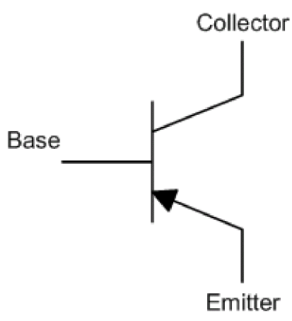
| Node | Port name |
|
TERM_IC |
Collector current terminal |
|
TERM_IB |
Base current terminal |
|
NODE_VC |
Collector voltage node |
|
NODE_VB |
Base voltage node |
|
NODE_VE |
Emitter voltage node |
Smoke parameters
| Smoke parameter | Maximum operating condition |
|
IB |
Maximum base current |
|
IC |
Maximum collector current |
|
VCB |
Maximum collector-base voltage (Maximum voltage difference between Collector and Base) |
|
VCE |
Maximum collector-emitter voltage (Maximum voltage difference between Collector and Emitter) |
|
VEB |
Maximum emitter-base voltage (Maximum voltage difference between Emitter and Base) |
|
SBSLP |
Secondary breakdown slope Secondary breakdown is the voltage breakdown between VC and VE at maximum collector current.
|
|
SBINT |
Secondary breakdown intercept |
|
SBTSLP |
Secondary breakdown temperature derating slope |
|
SBMIN |
Secondary breakdown derate percentage at maximum junction temperature |
Magnetic Core
These are a special type of template-based PSpice models that do not have smoke information. Therefore, the Node Mapping and Smoke Parameters frames are not available for these models.
Ins Gate Bipolar Transistor (IGBT)
Test Node Mapping
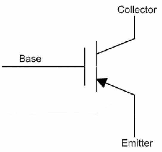
| Node | Port name |
|---|---|
|
TERM_IC |
Collector current terminal |
|
TERM_IG |
Gate current terminal |
|
NODE_VC |
Collector voltage node |
|
NODE_VG |
Gate voltage node |
|
NODE_VS |
Source voltage node |
Smoke parameters
| Smoke parameter | Maximum operating condition |
|
IG |
Maximum gate current |
|
IC |
Maximum collector current |
|
VCG |
Maximum collector-gate voltage (Voltage between Collector and Gate) |
|
VCE |
Maximum collector-emitter voltage (Voltage between Collector and Emitter) |
|
VGEF |
Maximum forward gate-emitter voltage (Voltage between Gate and Emitter) |
|
VGER |
Maximum reverse gate-emitter voltage |
Junction FET
Test Node Mapping
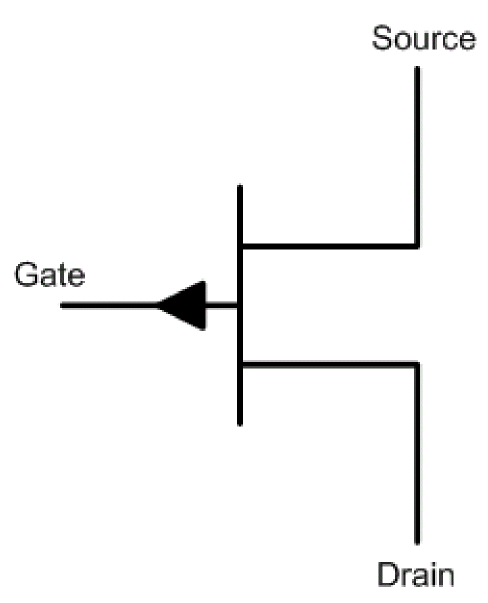
| Node | Port name |
|---|---|
|
TERM_ID |
Depletion current terminal |
|
TERM_IG |
Gate current terminal |
|
NODE_VD |
Depletion voltage node |
|
NODE_VG |
Gate voltage node |
|
NODE_VS |
Source voltage node |
Smoke parameters
| Smoke parameter | Maximum operating condition |
|
ID |
Maximum drain current |
|
IG |
Maximum forward gate current |
|
VDG |
Maximum drain-gate voltage (Maximum voltage between drain and gate) |
|
VDS |
Maximum drain-source voltage (Maximum voltage between drain and source) |
|
VGS |
Maximum gate-source voltage (Maximum voltage between gate and source) |
Operational Amplifier
Test Node Mapping
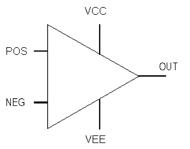
| Node | Port name |
|---|---|
|
NODE_POS |
Positive voltage source node (POS) |
|
NODE_NEG |
Negative voltage source node (NEG) |
|
NODE_VCC |
Positive voltage source node |
|
NODE_VEE |
Negative voltage source node |
|
NODE_GND |
|
|
TERM_POS |
Positive current terminal (POS) |
|
TERM_NEG |
Negative current terminal (NEG) |
|
TERM_OUT |
Output current terminal (OUT) |
Smoke parameters
| Smoke parameter | Maximum operating condition | Stands for... |
|
IPLUS |
Maximum input current (+) |
Maximum value of current at the POS terminal |
|
IMINUS |
Maximum input current (-) |
Maximum value of current at the NEG terminal |
|
IOUT |
Maximum output current |
Maximum value of current at the OUT terminal |
|
VDIFF |
Maximum differential VIN |
Absolute voltage difference between POS and NEG |
|
VSMAX |
Maximum supply voltage difference |
Voltage difference between NODE_VCC and NODE_VEE |
|
VSMIN |
Minimum supply voltage difference |
Voltage difference between NODE_VEE and NODE_VCC |
|
VPMAX |
Maximum input voltage (+) |
Voltage difference between NODE_POS and NODE_VCC |
|
VPMIN |
Minimum input voltage (+) |
Voltage difference between NODE_VEE and NODE_POS |
|
VMMAX |
Maximum input voltage (-) |
Voltage difference between NODE_NEG and NODE_VCC |
|
VMMIN |
Minimum input voltage (-) |
Voltage difference between NODE_VEE and NODE_NEG |
MOSFET
Test Node Mapping
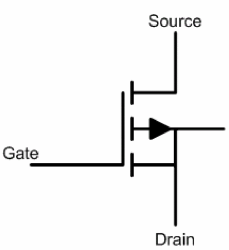
| Node | Port name |
|---|---|
|
TERM_ID |
Drain current terminal |
|
TERM_IG |
Gate current terminal |
|
NODE_VD |
Drain voltage node |
|
NODE_VG |
Gate voltage node |
|
NODE_VS |
Source voltage node |
Smoke parameters
| Smoke Parameter | Maximum Operating Condition |
|
IG |
Maximum forward gate current |
|
ID |
Maximum drain current |
|
VDG |
Maximum drain-gate voltage (Maximum difference between NODE_VD and NODE_VG) |
|
VDS |
Maximum drain-source voltage (Maximum difference between NODE_VD and NODE_VS) |
|
VGSF |
Maximum forward gate-source voltage |
|
VGSR |
Maximum reverse gate-source voltage |
Voltage Regulator
Test Node Mapping
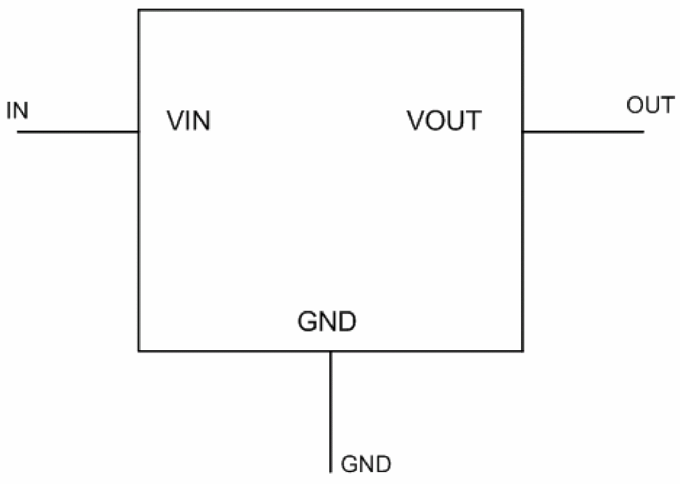
| Node | Port name |
|---|---|
|
NODE_IN |
Input voltage node (IN) |
|
NODE_OUT |
Output voltage node (OUT) |
|
NODE_GND |
Ground voltage node (GND) |
Darlington Transistor
Test Node Mapping
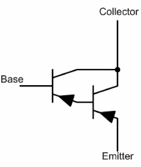
| Node | Port name |
|---|---|
|
TERM_IC |
Collector current terminal |
|
TERM_IB |
Base current terminal |
|
NODE_VC |
Collector voltage node |
|
NODE_VB |
Base voltage node |
|
NODE_VE |
Emitter voltage node |
Smoke parameters
| Smoke parameter | Maximum operating condition |
|
IB |
Maximum base current Max(TERM_IB) |
|
IC |
Maximum Collector current Max(TERM_IC) |
|
VCB |
Maximum collector-base voltage Max(NODE_VC -NODE_VB) |
|
VCE |
Maximum collector-emitter voltage Max(NODE_VC -NODE_VE) |
|
VEB |
Maximum emitter-base voltage Max(NODE_VE -NODE_VB) |
|
SBSLP |
Secondary breakdown slope Secondary breakdown is the voltage breakdown between VC and VE at maximum collector current.
|
|
SBINT |
Secondary breakdown intercept |
|
SBTSLP |
Secondary breakdown temperature derating slope |
|
SBMIN |
Secondary breakdown derate percentage at maximum junction temperature |
- Depending on the license available, you will access either PSpice A/D or PSpice Simulator.
- In this guide, design entry tool is used for both OrCAD X Capture and Design Entry HDL. Any differences between the two tools is mentioned, if necessary.
This is the standard PSpice device letter notation. Refer to the PSpice A/D Reference Guide.
Model Editor supports only .SUBCKT models that were created using the Model Editor. However, you can edit the text of a .SUBCKT model created manually or by another tool using the Model Editor. When you load a .SUBCKT model that the Model Editor did not create, the Model Editor displays the text of the model for editing.
To find out more about Magnetic Core models, see PSpice A/D Reference Manual.
For template-based PSpice models the model text is read-only and cannot be edited using the Model Editor.
This is the standard PSpice device letter notation. Refer to the PSpice A/D Reference Guide.
A template-based magnetic core model is a SpicePlus model. To find out more about Magnetic Core models, see PSpice A/D Reference Manual.
View the next document: 05 - Creating Parts and PSpice Model Libraries
If you have any questions or comments about the OrCAD X platform, click on the link below.
Contact Us