OrCAD X Create/Remove Xnet Step-by-Step Guide
Key Takeaways
-
Xnets are a tool to override standard net assignment from netlisting, which can complicate length-matching efforts.
-
Users start by adding the appropriate property to a part instance in the schematic before setting up Xnet associations in the layout.
-
Xnets are easy to set up, remove, and users can suppress them for part/component instances where they are unnecessary.
OrCAD X create/remove Xnet tools length-match transmission lines that span more than 2 pins.
Modern ECAD tools can rapidly netlist designs containing thousands of components and unique interconnections. The latter, colloquially known as “nets,” will inherit designated names or have their name algorithmically generated by the software. This system is often sufficient, but it can run into issues with signals that span additional pins from driver to load. For example, data lines often require length-matching to avoid runtime errors, but comparing the length-matched signals from start to finish can be difficult when they split across multiple smaller nets.
Xnets rectify this situation by allowing the user to define connections of multiple nets, making it much easier for the designer to compare lengths during routing. OrCAD X create/remove Xnet tools makes it easy to add this functionality to the schematic, update the layout, and suppress the Xnet parameter (if necessary).
OrCAD X Create/Remove XNet Process Overview
|
Create |
Remove |
||
|
|
OR |
|
OrCAD X Create/Remove Xnet Process Screenshot Guide
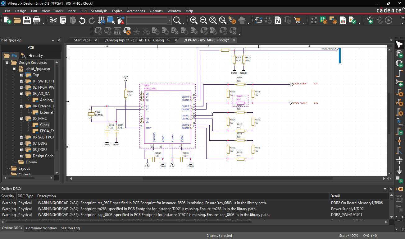
Xnets are helpful implementations within the schematic and layout that eXtend nets where a passive divides a unique net into two individual nets. A user-defined Xnet makes length-matching easier: instead of manually adding the individual net component lengths when the net between a driver and receiver (as an example) contains an intermediate terminating resistor, the Xnet bundles the lengths together and presents the combined net lengths as a single value. An Xnet can span two or more nets; users will indicate Driver, Load, and Other (intermediary) pins in the SI Design Setup. Finally, users can add an Xnet delay property to transmission lines to simulate signal transmission timing more accurately.
Let’s walk through the process of Xnets, starting with creation:
-
In OrCAD X Capture, select the part functioning as the load/driver. Right-click, and select “Edit Part” from the dropdown menu.

Select the “Edit Part” command after right-clicking on a component. - Scroll to the bottom of the “Part Properties” panel. At the bottom, select the “Add New Property” button.

Select the “Add New Property” button in the bottom left corner of the “Part Properties” panel. -
Select “Class” from the dropdown for the new Part Property and enter “discrete” as the part parameter. Select the blue “Add New Property” checkmark.

New Part Property in Part Property panel. -
Close the part instance file, and select “Update All” when prompted to save.
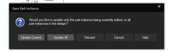
Select “Update All” to add the “Part Property” to every component instance. -
Repeat the process if necessary for the pins of the corresponding load/driver component.
-
Sync the updates to the layout in OrCAD X PCB Editor. From here, navigate to “Setup > More” in the top toolbar and select “SI Design Setup” from the dropdown.
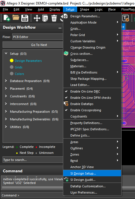
Select the “SI Design Setup” tool from the “Setup > More” dropdown in the top navbar. -
In the “Setup Category Selection” window, uncheck all setup categories except “Xnets” and “Run Audit upon completion of each setup category,” then click “Next.”
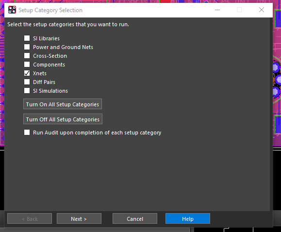
Uncheck all Setup Categories except for Xnets -
Uncheck all nets and expand the design's netlist. Select the discrete nets intended for Xnet designation, then click “Next.”
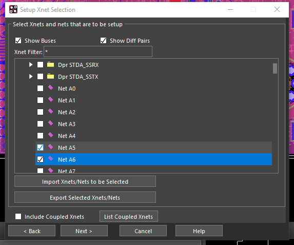
Select the nets for Xnet association from the netlist.
Removing Xnets follows a similar process: if designers wish to remove all Xnets from load/driver pins, simply remove the “Class” property in the “Edit Part” menu of OrCAD X Capture. Select “Update All” when saving the part library file, then update the layout from the schematic to remove all Xnets. However, users may only want to remove Xnets from specific part instances without changing other Xnets within the design. In that case, users can suppress Xnet by component instantiation at the schematic or layout level of the design.
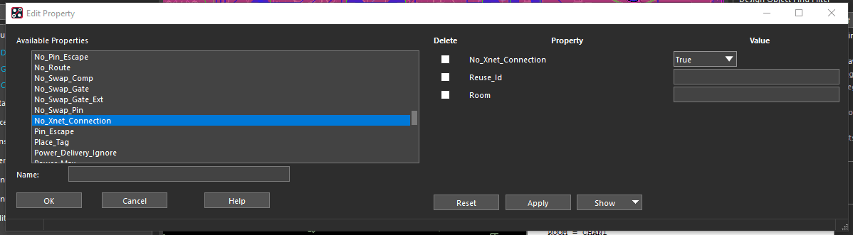
Overriding part Xnet capabilities in the Schematic Properties Editor.
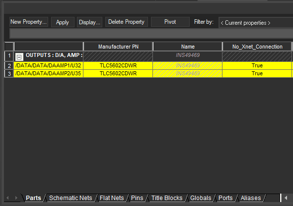
Overriding component Xnet capabilities in the OrCAD X PCB Editor Edit Properties window.
Cadence Solutions for Complex Layouts
The OrCAD X create/remove Xnet tool assists designers with length-matching when signals span pins between load and driver that “split” a continuous signal transmission into multiple smaller nets. Fortunately, the Xnet option allows designers to override the default net assignment so designers can more easily length-match signals and improve runtime performance. The new OrCAD X platform contains many tools that help designers reduce turnaround times for even the most cutting-edge layouts. Interested in learning more? See how Cadence PCB Design and Analysis Software can improve your ECAD workflow.
Leading electronics providers rely on Cadence products to optimize power, space, and energy needs for a wide variety of market applications. To learn more about our innovative solutions, talk to our team of experts or subscribe to our YouTube channel.