Addressing the Challenges of PCB Design for Manufacturing FAQ
Here are some comprehensive answers to all the questions asked in our recent webinar.
Live DOC | Manufacturing | DesignTrue Portal | General
Live DOC
Currently, Live DOC only supports black and white with plans to support full color PDF in the future.
Not yet, however full 3D views are coming in an upcoming release.
Unfortunately, no it cannot. The Altium Draftsman format is not compatible with Live DOC.
Currently Live DOC supports intelligent PDF generation, so for example you can search for certain numbers or words within the document.
No, you do not. Live DOC supports templates, so once you come up with a good format that you want to use, you can save it as a template and open any design with it as the saved template will auto generate the latest data within your current design.
The Live DOC document can be versioned, but remember the document is “live” linked to the PCB database. The placed drawing objects are dynamically linked to the PCB making the drawing object version always match the current version of the PCB. In short, the revision control is done at the board level.
Manufacturing
Yes, you can control the thickness and the materials within the stackup, as well as the constraint rules for all the stackups.
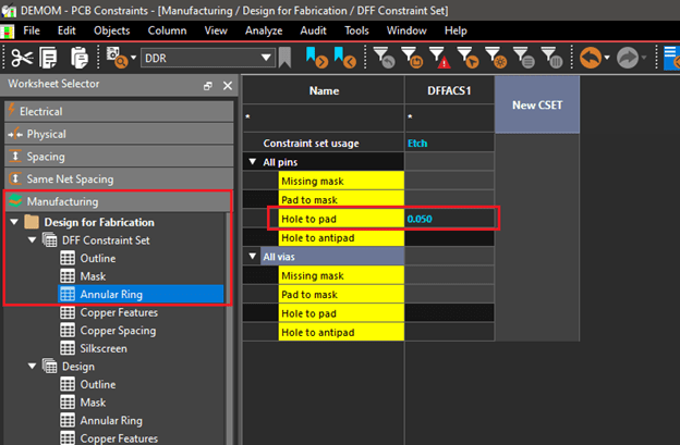
OrCAD X PCB layout does not take tolerances into account – either manufacturing or material choices. The DFM checks are based solely on the values entered into Constraint Manager. Below is an example of a 2 mil annular check in DFM.
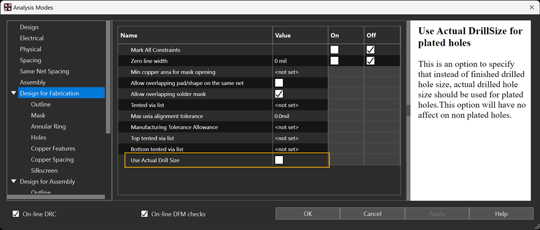
In 23.1, the Padstack Editor was updated to support both Finished and Actual Drill Sizes for Padstacks and we added an option in 23.1 ISR2 to use the Actual Drill for Hole Checks in DesignTrue. This is only a DesignTrue DFF Check change, standard Spacing Domain Hole Checks are still using Finished Hole Size.
The best thing to do is to set up your manufacturing rules within the constraint manager to flag the error. Just like the DRC, it’s up to the designer to determine what are "stop" errors verse what can be waived - the tool just flags the problem.
DesignTrue Portal
To access the DesignTrue DFM Customer Portal, you can sign up here. If you’re having any issues with access or requesting rule sets, feel free to contact the Cadence support team for help.
The best place to start is working with your fabricator or request an initial rule set from one of our participating DesignTrue DFM fabricators via the DFM portal. Here is a walk-though demo you can refer to that shows you how to request rules from a fabricator.
Yes, the rules have been vetted out with fabricators. DesignTrue DFM has been in the market for almost 10 years and numerous companies have manufactured designs using DesignTrue with positive feedback. In terms of setting up the rules, it’s best to work with your fabricator as they can guide you with what criteria they will be checking your designs against. Some fabricators may have the capabilities to create rule decks for you and share them, however if you’re creating from scratch, and defining for a certain fabricator, certain processes and stackups, you can always reuse your rules where possible for any design.
General
Yes, all constraint rules can be exported and imported for reuse between designs.
Your files are saved within your working directory.
Once you’ve entered in your constraints within the constraint manager, simply select File > Save or Ctrl+S and the rules are automatically saved.
There are plans to add an impedance table object to Live DOC.
Our higher end Allegro X products support constraint locking.
Unfortunately, we do not support the import of Valor rules. This is because the rule sets between the systems do not match.
IPC-2581 is the latest and greatest XML format, it has the ability to embed XML attributes. ODB++ can do that too, but with IPC-2581, the capability of XML allows you to eliminate fab notes and allows you to include attribute within your XML file. One of the advantages that it provides is that it allows us to transfer smart intelligent information versus transferring information from one piece of paper for someone to read and manually enter into another software application. The other advantage is that customers have requested stackup data in 2581 format so that they don’t have to manually input information from a PDF file for a stackup update. Moreover, I’d like to see IPC-2581 expanded and really utilize the intelligent capabilities associated with it.
Yes, we at Summit can certainly provide preliminary information for you to start with. However, keep in mind that we still need all the design data. We need to look at the copper weights, the design itself to finalize any impedance.