Circuit Troubleshooting Techniques: A Practical Guide
Key Takeaways
-
Physical troubleshooting involves inspection and testing of components and connections to find hardware faults.
-
Simulation tools like PSpice in OrCAD X allow you to easily identify and resolve design flaws before manufacturing.
-
A combination of physical testing and simulation round out some good circuit troubleshooting techniques.

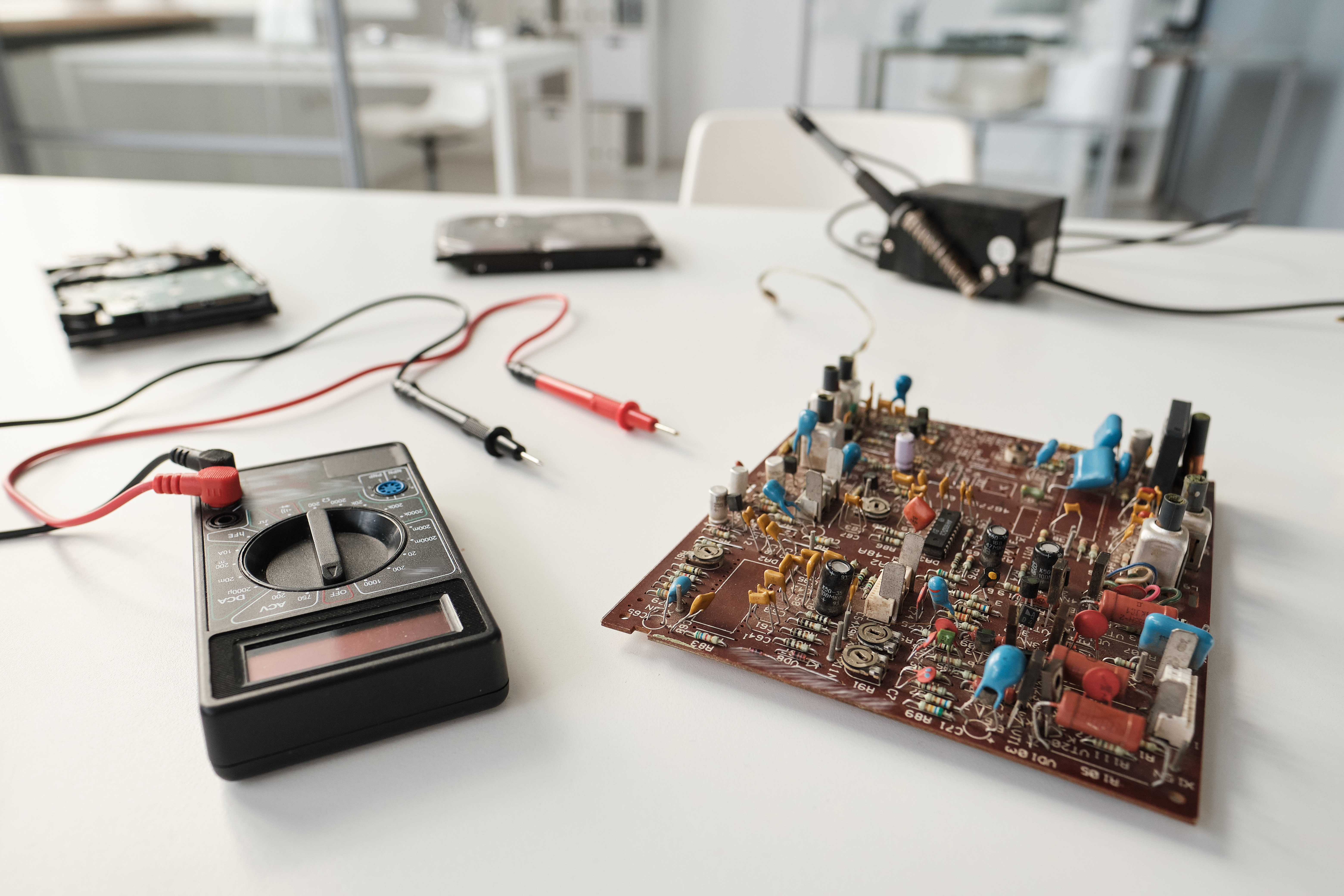
A multimeter is one of the most useful tools when there’s a physical issue with your circuit
A single malfunctioning component or a faulty connection in a circuit can disrupt the entire system, leading to unexpected behavior or complete failure. Circuit troubleshooting techniques involve methodically identifying, isolating, and fixing faults in an electronic circuit. Many PCB issues occur due to human error in the manufacturing process, given the precision required for PCBs to function correctly. However, effectively diagnosing and resolving issues can be managed through two prongs:
-
addressing physical hardware problems and;
-
identifying design-related flaws.
While physical troubleshooting focuses on inspecting components, connections, and power supplies, design troubleshooting emphasizes the importance of circuit simulation and analysis. This is where a tool like Cadence PSpice comes into play. PSpice is a leading simulation tool used to model and analyze the behavior of electronic circuits, allowing for the investigation of timing violations, signal integrity problems, power distribution errors, and more.
Common Design Analysis Faults & Mitigation Techniques
|
Fault Area |
Examples |
Analysis & Mitigation |
| Timing Issues |
- Setup and hold violations |
Simulate the circuit to verify that all timing requirements are met.
|
| Signal Integrity Problems |
- Reflections from unmatched impedance |
Simulate the circuit to analyze signal integrity issues, such as reflections, crosstalk, and ringing.
|
|
Noise Sensitivity |
- Inadequate filtering or shielding |
Simulate the circuit to analyze its susceptibility to noise.
|
| Power Distribution Problems |
- Inadequate decoupling capacitors |
Simulate the circuit to analyze its power consumption and distribution.
|
|
Thermal Issues |
- High power dissipation |
Simulate the circuit to analyze its thermal behavior.
|
Physical Circuit Troubleshooting Techniques
As mentioned, problems may arise with your PCB’s physical components, connections, and manufacturing defects. These issues require hands-on troubleshooting.
Common PCB Physical Troubleshooting Areas
|
Fault Area |
Examples |
|
Component Failures |
- Resistors drift in value |
|
Connection Issues |
- Broken/cut PCB traces |
|
Power Supply Problems |
- Unstable voltage regulators |
|
Manufacturing Defects |
- Solder bridges |
|
Environmental Factors |
- High humidity |
|
SMT Issues |
- Tombstoning |
Initial Inspection For Circuit Troubleshooting
-
Visual Inspection: Examine the circuit board for obvious damage, such as burned components, broken traces, loose connections, or corrosion.
-
Look for any broken or corroded solder joints.
-
Check for short circuits or bridging of pins.
-
Inspect capacitors for bulging or leaks, as these are common points of failure.
-
Verify the Power Supply: Use a multimeter to check if the power supply is delivering the correct voltage levels to the circuit. Also, verify that the ground connections are properly established.
-
Measure input voltage using a multimeter.
-
Verify ground connections are properly established.
-
Check for voltage drops across key points in the circuit.
Signal and Component Testing
-
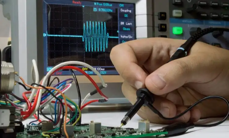
Signal Tracing: Use an oscilloscope to trace signals through the circuit, comparing them to expected waveforms.
-
Set the oscilloscope to the proper voltage and time scales.
-
Measure the amplitude, frequency, and shape of the signal.
-
Compare the measured signal with the expected signal from the circuit diagram.
-
Component Testing: Test individual components to ensure they are functioning within their specifications. A multimeter can be used to test resistors, capacitors, diodes, and transistors.
-
Each component should register at or below the stated component value, which signals that there isn't an issue for that part.
-
However, if the component value registers higher than the indicated value, that signals a problem.
Advanced Troubleshooting Techniques
-
Compare with a Known Good Circuit: If available, compare the voltage and signal readings of the faulty circuit with a working one.
-
Visually compare the two PCBs to look for any glaring issues, such as burn marks or misplaced components.
-
Compare the two PCBs' behavior and functionality using a multimeter, such as the registered component values.
-
Stimulus-Response Testing: Inject a known signal into the circuit and observe the output to reveal problems with signal processing functions.

Design Troubleshooting Techniques
One of the most effective ways to minimize the need for physical troubleshooting is to proactively simulate your circuit's behavior with Cadence's PSpice simulation tool. By creating a virtual model of your circuit in PSpice, you can analyze its response to various inputs and identify potential issues through the following analyses:
-
DC Sweep Analysis: Adjust component values (e.g., resistor value, current, or voltage) to observe their impact on the circuit.
-
AC Sweep Analysis: Evaluate the frequency response of the circuit, analyzing gain and phase across a specified range.
-
Transient Analysis: Simulate how the circuit responds to changes over time, which is useful for verifying dynamic behavior.
-
Sensitivity Analysis: Identify critical components by testing circuit performance across component tolerance ranges.
-
Monte Carlo Analysis: Predict production yield by performing statistical analysis on component variations.
Troubleshooting with PSpice Simulation
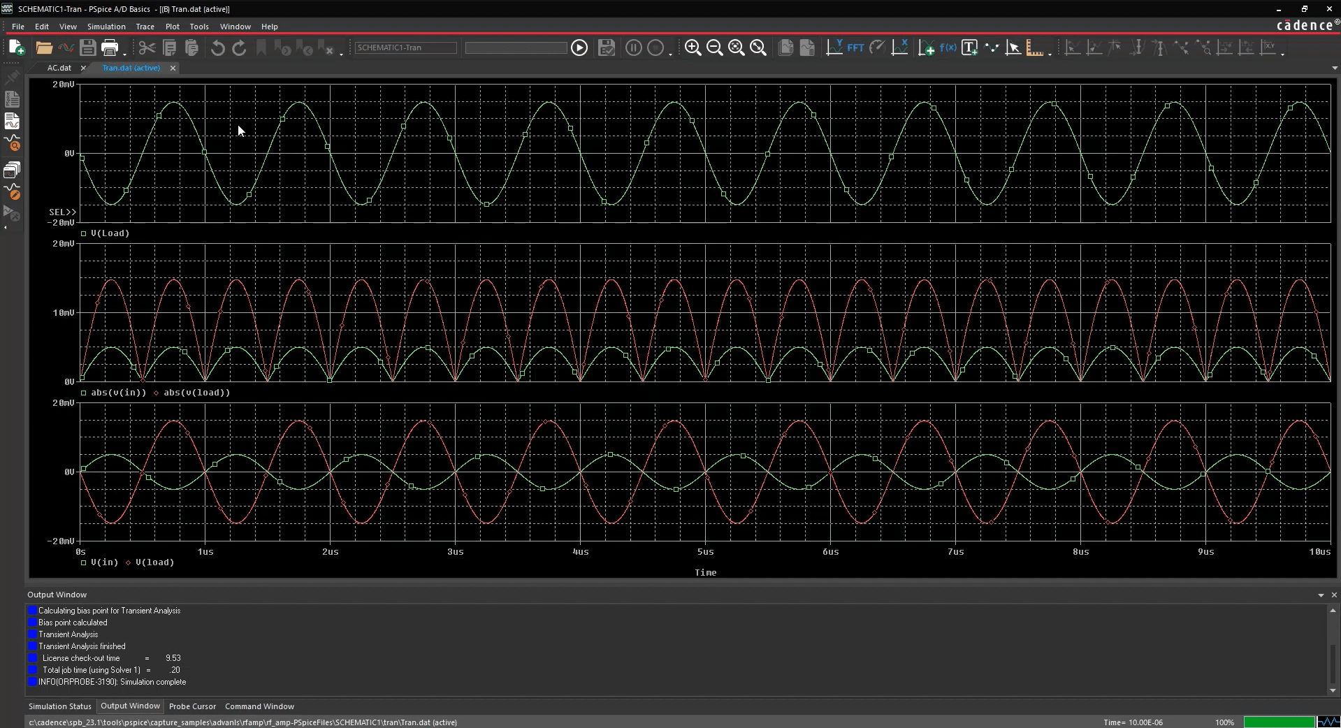
After building your physical circuit, use PSpice to compare simulated results with actual measurements. By placing probes at critical nodes in the simulation, you can generate waveform plots of voltages and currents, making it easy to see if your physical circuit’s behavior aligns with the expected response.

Cadence’s PSpice circuit simulation tool
Here's an example of the comparison of circuit troubleshooting techniques using PSpice:
-
Simulate the Circuit: Build the circuit in OrCAD X Capture and run a transient simulation to obtain voltage and current waveforms at key nodes in PSpice.
-
Measure the Physical Circuit: Use an oscilloscope to measure the voltage and current waveforms at the corresponding nodes in the physical circuit.
-
Compare Waveforms: Compare the simulated and measured waveforms to visually identify any differences in amplitude, frequency, or shape.
-
Isolate the Issue: If discrepancies exist, use probes on individual components and connections to determine the root cause.
If discrepancies arise when comparing simulated and actual circuit responses, these can help identify specific issues in the physical circuit, such as incorrect component values, poor connections, or layout-related problems.
The integration between PSpice and OrCAD X PCB design software allows for not only simulation and verification but also real-time design adjustments when troubleshooting your circuits. OrCAD X makes it easy to review the circuit schematic for potential design flaws, such as incorrect component values, improper connections, or missing components.
Knowing correct circuit troubleshooting techniques aids in efficient PCB design and maintenance. Cadence OrCAD X provides a comprehensive platform for both physical and design-related troubleshooting. From simulating circuit behavior with PSpice to identifying layout flaws in the PCB editor, OrCAD X equips designers with the tools they need to diagnose and resolve issues effectively. Start your free trial of OrCAD X today!
Leading electronics providers rely on Cadence products to optimize power, space, and energy needs for a wide variety of market applications. To learn more about our innovative solutions, subscribe to our newsletter or our YouTube channel.