Understanding Simple DC Power Supply Circuits
Key Takeaways
-
A basic DC power supply circuit converts AC from the power grid into a stable DC voltage, involving components like transformers, rectifiers, and regulators to ensure a smooth and constant output.
-
Each component has a specific role, from stepping down voltage and isolating circuits (transformer), converting AC to DC (rectifier), smoothing voltage fluctuations (capacitors), and maintaining stable voltage output (linear regulator).
-
Linear regulators adjust resistance to maintain constant voltage, with feedback loops for fine-tuning.
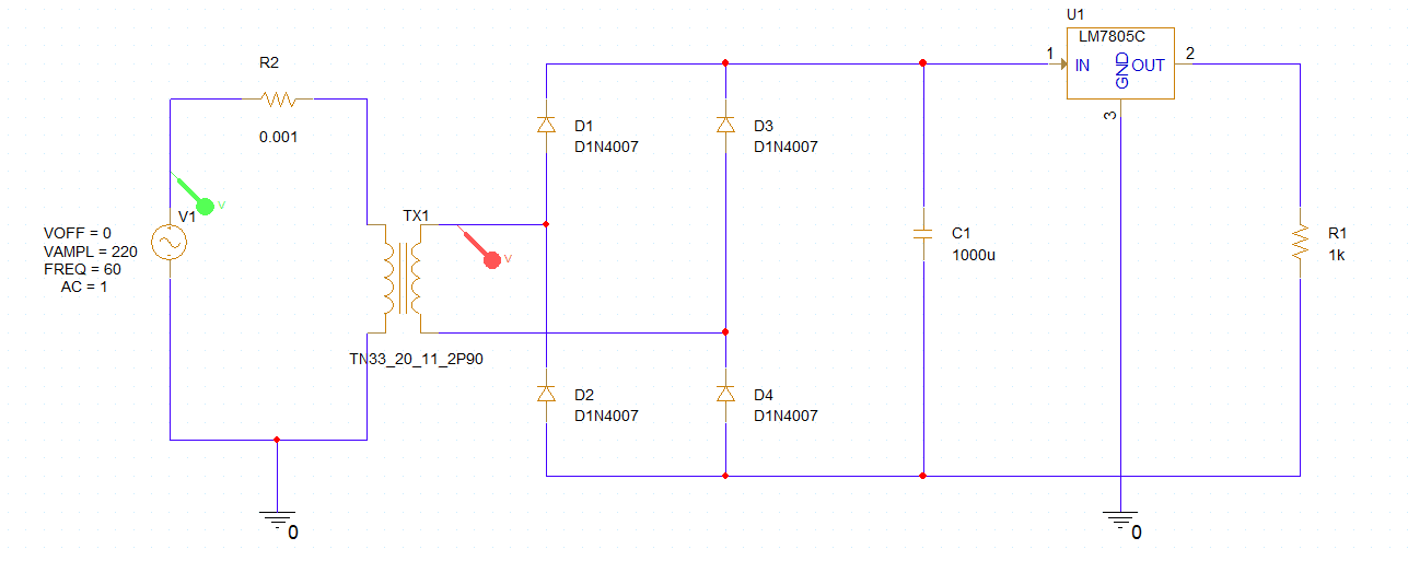
Simple DC power supply circuit
Direct Current (DC) power supply circuits are critical to power many electronic devices, from simple gadgets to complex machinery. A simple DC power supply circuit converts Alternating Current (AC) from the power grid into a stable DC voltage. Understanding how a simple DC power supply circuit works is fundamental for both electronics hobbyists and professionals. This article provides a concise overview of the key components and functions of a simple DC power supply circuit.
Simple DC Power Supply Circuit Summary
|
Component |
Function |
|
AC Input |
Connection to the AC source such as the mains electricity supply. |
|
Transformer |
Steps down the high AC voltage to a lower level and provides isolation between the input and the rest of the power supply. |
|
Full Rectifier |
Converts the AC voltage from the transformer to a high-ripple pulsating voltage using a configuration of diodes. |
|
Filter Capacitor |
Smooths out the pulsating voltage from the rectifier to reduce AC ripple on top, resulting in a smoother DC voltage. |
|
Linear Regulator |
Provides a stable DC output voltage by dissipating excess voltage as heat and adjusting resistance in response to load and input. |
|
Feedback |
The two resistors are used as a feedback loop to improve regulation by feeding a portion of the output voltage back to the regulator for adjustments to maintain constant voltage. The variable resistor allows for tuning of the feedback loop, which in turn affects the final VOUT |
|
Second Capacitor |
Reduces ripple when the load changes |
|
Output |
The final regulated DC voltage that is provided to electronic devices. |
Notes on the Linear Regulator
Linear regulators are components often used in power supplies to achieve precisely regulated and adjustable voltage/current outputs. The choice of integrated circuit (IC) is critical in this context, with factors such as the required output voltage, the needed output current, and the load and line regulation capabilities playing pivotal roles. The IC's selection should consider the maximum current it can handle, the range of voltage desired, and the range of input voltage it can accept.
-
Load Regulation refers to the ability of a power supply to maintain its specified output voltage despite changes in the load. It measures how much the output voltage changes when the load on the power supply varies from minimum to maximum, expressed as a percentage of the output voltage or in volts. This parameter is crucial for ensuring consistent performance in varying load conditions.
-
Line Regulation is a measure of a power supply's ability to maintain its specified output voltage despite changes in the input voltage. It quantifies the stability of the output voltage over a range of input voltages, often expressed as a change in output voltage per unit change in input voltage (e.g., mV/V). Line regulation ensures that fluctuations in the input supply do not affect the output voltage, providing stable operation across different power conditions.
Switch Mode Power Supply Instead of Linear Regulator
A Switched-Mode Power Supply (SMPS) can be used instead of a linear regulator. It is more complicated and incorporates a switching regulator to convert electrical power efficiently. By rapidly switching on and off, it controls and stabilizes the output voltage, enabling both high efficiency and compact size compared to traditional linear power supplies.
Transformerless SMPS power supplies have gained popularity due to their high efficiency and significant power in small sizes. However, constructing an SMPS power supply circuit from scratch is not recommended for beginners. It requires a deep understanding of the technology, making it a project best suited for engineers and hobbyists with extensive knowledge in the area.
Transformer Notes
The transformer, featuring two sets of coils — one designated as primary and the other as secondary — plays a crucial role in isolation and voltage reduction. When either 220V or 120V from the mains is applied to the primary coil, it is then conveyed to the secondary coil, resulting in a reduced voltage being generated in the secondary coil's windings. The ratios of the windings in the transformer contribute to the step-down. Whether it’s no step-down (1:1 ratio of windings), halving (1:2), or another ratio best for the desired application and operational voltage.
Master your DC power supply circuit designs with OrCAD X and explore its intuitive tools tailored for seamless PCB designs. From schematic capture to layout, OrCAD X streamlines your process, ensuring precision and efficiency.
Leading electronics providers rely on Cadence products to optimize power, space, and energy needs for a wide variety of market applications. To learn more about our innovative solutions, talk to our team of experts or subscribe to our YouTube channel.