PCB Thermal Design Guide: Tips For PCB Analysis and Performance
Key Takeaways
-
Learn how to select appropriate board materials for high-heat scenarios.
-
Methods for component layout to maximize heat transfer away from your board.
-
Tips and tricks for optimizing your PCB’s routing and trace specifications for efficient thermal performance.

As circuits become faster and smaller, thermal issues are more prevalent than ever, making it important to design your board to deal with these high-heat scenarios
Electronics are becoming faster, smaller, and used in more demanding environments. Miniaturized ICs and SMDs operate at higher frequencies and require more power. Increased current demands cause voltage drops across resistive elements, generating heat and leading to temperature rises and hotspots. Over half of electronic component failures now stem from heat-related stress. To develop high-quality circuit boards, it is now more important than ever to consider the safety and temperature of your system using a PCB thermal design guide for efficient performance. In this article, we will present some key strategies and solutions for PCB design for thermal performance improvement.
[CELSIUS THERMAL SOLVER VIDEO LINK HERE]
Thermal conductivity refers to a material's ability to transfer heat. In PCBs, it enables the movement of heat from components to outside the system. Planning ahead for high thermal sources before circuit board production enhances device reliability, especially in small or high-current devices prone to heat spots. Designing for thermal performance is key for next-generation devices.
Industries like gas and oil, avionics, and automotive operate in harsh environments and are especially susceptible to high thermal conditions. Whether used in industrial equipment, power electronics, or embedded systems, designing circuit boards with high thermal performance requires special considerations in manufacturing, layout, routing, and thermal analyses to keep boards cool.
Key PCB Thermal Design Guide Tips
|
Aspect |
Tip/Recommendation |
Details/Notes |
|
PCB Material Selection |
Choose materials with appropriate Glass Transition Temperature (Tg) and thermal conductivity for your environment. |
|
|
Component Placement |
Place temperature-sensitive components in cooler areas, such as the edges or bottom of the board; high-power components should be evenly distributed. |
|
|
Component Selection |
Select components with higher thermal efficiency and suitable temperature ratings. |
|
|
Trace Design |
Use wider traces for high-current paths; keep trace lengths short and corners rounded or at 45 degrees. |
|
|
Ground and Power Planes |
Utilize large copper ground and power planes to act as heat sinks and enhance heat dissipation. |
|
|
Thermal Vias |
Implement thermal vias to transfer heat between PCB layers and away from hotspots. |
|
|
Thermal Standards Compliance |
Adhere to IPC, UL, and IEC standards for thermal management in PCB design. |
|
|
Thermal Analysis |
Use thermal simulation and analysis tools to identify and mitigate potential thermal issues early in the design process. |
|
|
Protective Coatings and Encapsulation |
Consider using thermal interface materials, protective coatings, or encapsulants to enhance heat dissipation. |
|
|
Cooling Mechanisms |
Integrate additional cooling solutions when necessary, such as heat sinks, fans, or thermal pads. |
|
PCB Materials and Board Operating Temperature

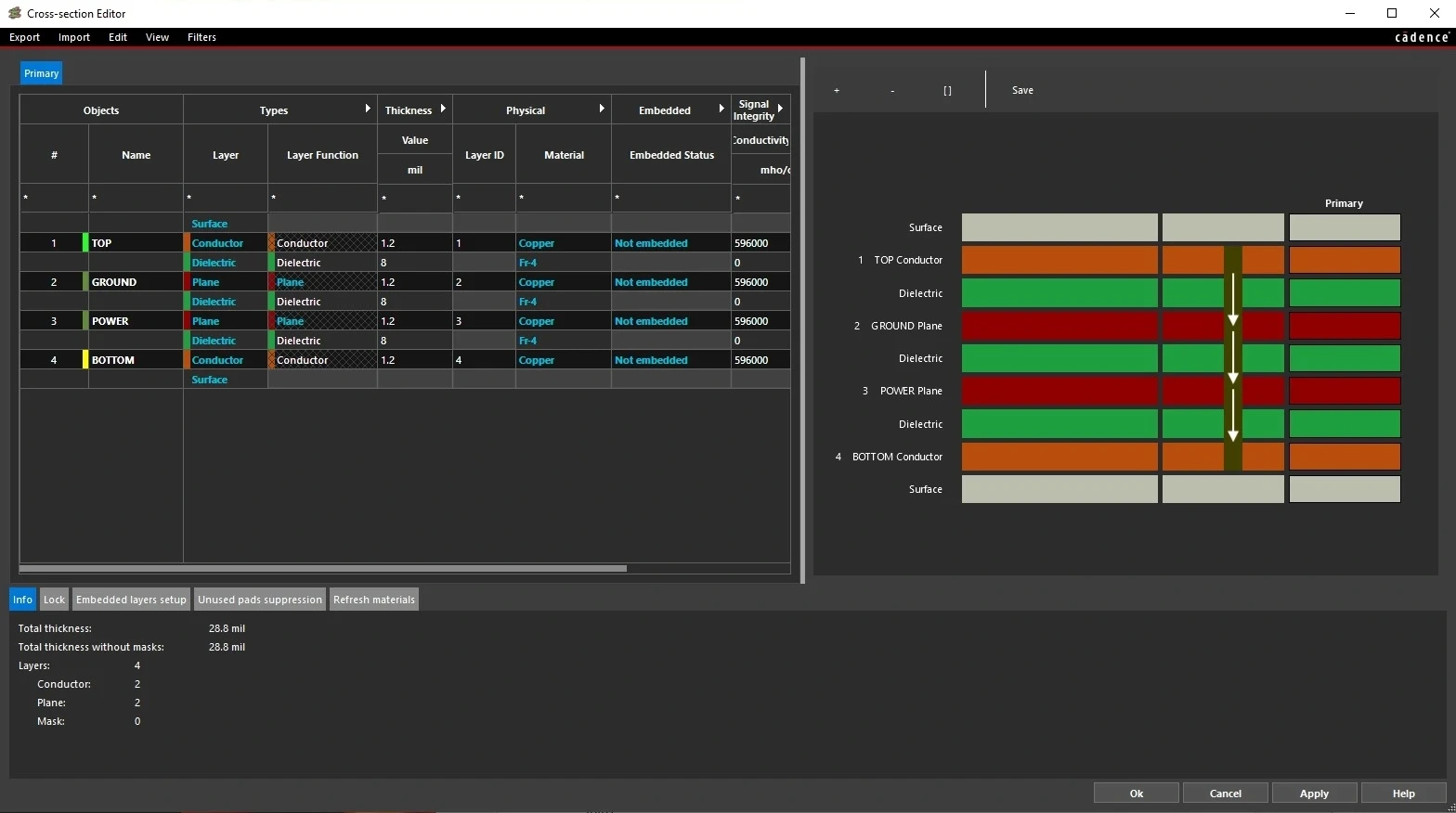
The Cross-section Editor within Allegro X that shows a four layer board. Changing the dielectric material can result in better thermal performance.
Before laying out your components, it’s essential to consider your board construction and material, as it plays a large role in distributing heat.
If your board is operating in a particularly hot environment, knowing the material’s operating temperature, and specifically the TG rating (glass transition temperature) is critical.
-
FR-4, the most common PCB material, is rated to operate up to 130 degrees before the glass begins to transform to a liquid state.
-
If you plan on operating at higher temperatures, consider using a different material such as Shengyi S1000-2, ARLON 85N, or ITEQ IT-180A.
In cases where your board produces an especially large amount of heat, using an alternative substrate with higher thermal conductivity is your best bet. Ceramics, for example, have higher thermal conductivity and their mechanical properties can be tuned, which can accommodate stress that is introduced in thermal cycling.

Table outlining thermal conductivity for PCB materials including FR4, Alumina, Aluminum Nitride, and Beryllium Oxide
Compared to FR-4, the thermal expansion coefficient of ceramic is closer to that of silicon chips, thus not requiring an interface material. Other hybrid materials like PTFE and non-PTFE thermoset resin systems with ceramic fillers may offer lower dielectric losses as well.
The effective thermal conductivities of a PCB depend on the total thickness and the individual thicknesses of copper and glass-epoxy. Using a metal core for your FR4 or other board can help transport heat quicker throughout due to the high conductivity of metal. Aluminum or galvanized copper are commonly used.
-
Aluminum is a bit cheaper
-
Copper is more thermally efficient
To accelerate heat dissipation even more, consider using protective coatings or other encapsulating materials.

Knowing how to select specific components that are thermally efficient is crucial to keeping your board operating in high-heat conditions
PCB Thermal Design Guide For Optimal Performance
Here, we’ve detailed key points of our PCB thermal design guide for component layout and routing. Key PCB design considerations include:
Temperature-Sensitive Components
Components especially sensitive to temperature should be placed in the location with the lowest temperature, such as the bottom of the board. Make sure to keep them away from components with high heat productivity (e.g., frequency transistors, hyper-scale ICs, microprocessors). These heat-producing components, on the other hand, should be placed in locations with the best heat dissipation (wide copper traces and polygon fills, which we’ll delve into in the upcoming section). Place passive components that generate less heat and are more temperature-sensitive near the edges, with high-powered components in the center. Following a PCB thermal design guide will ensure that high-heat-producing components are placed strategically for optimal heat dissipation.
High-Power Components
High-power components, such as high-powered resistors and voltage regulators, will create a lot of heat, and bunching them up can create hotspots. Distribute your high-power components throughout the board to avoid creating specific hotspots.
Component Selection
Over half of the heat generated is brought to the board through component leads. Consider using metal-plating holes and keeping leads short. Additionally, when selecting components with high power consumption, choose components with a larger cross-sectional area and high pin counts for better heat transfer. Using screws to mount the PCB can also allow for thermal access to the base of the system, distributing the heat more effectively.
When operating at high current, components like resistors, transforms, switching FETs, driver ICs, and control ICs create local temperature increases. Many of these components may not be designed to function in extreme heat and may break down at operating temperatures. Make sure to verify temperature ratings on your components when selecting them to prevent your board from overheating and failing.
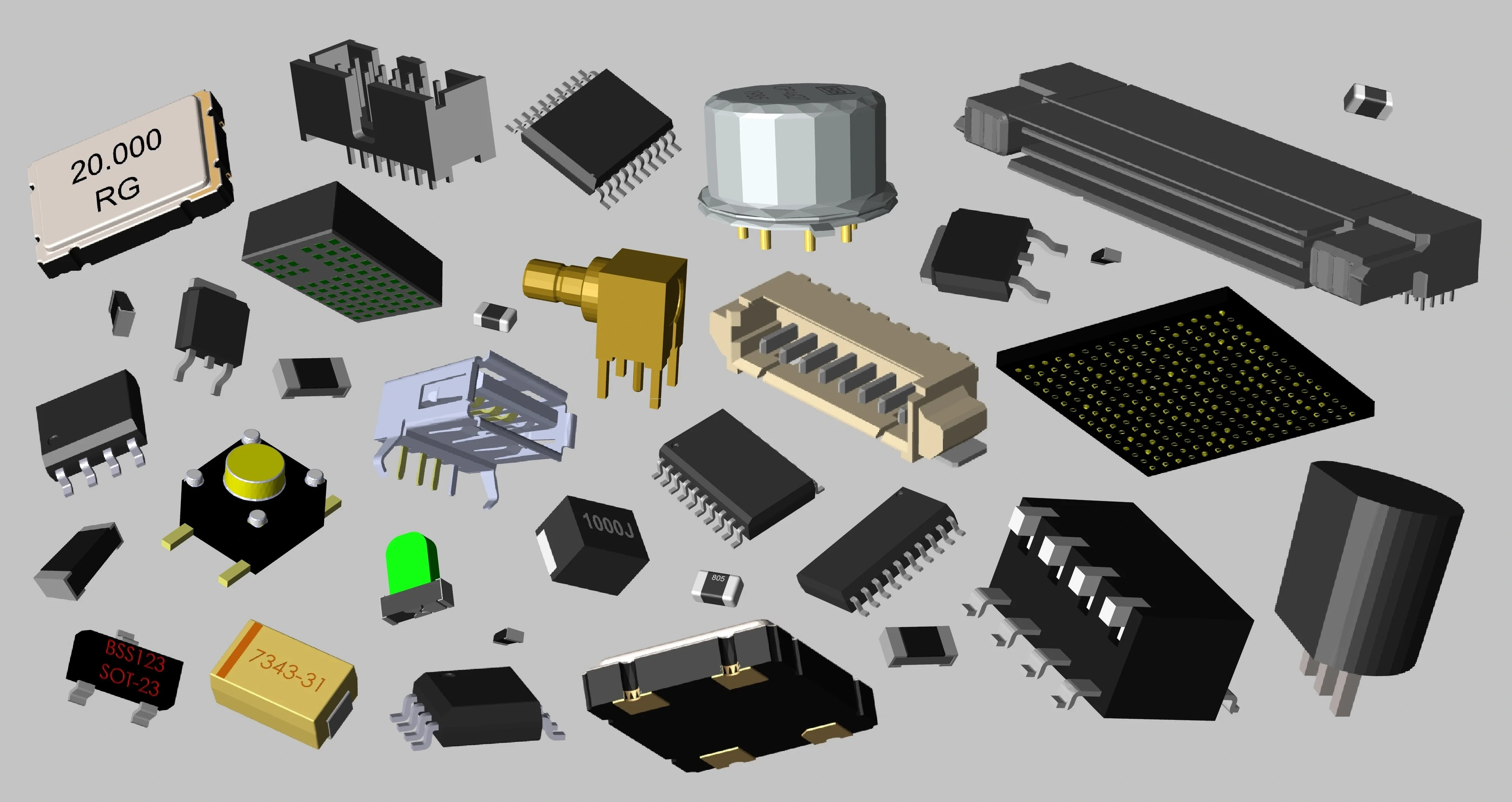
Keep in mind that as components become smaller they are able to dissipate less heat. A MOSFET in an SOT-23 package, for example, has less surface area for heat dissipation compared to a TO-220 package MOSFET.
Trace Length and Width
For power traces with high current, keep them as short as possible and away from other sensitive circuitry. Reducing the length that the current has to flow minimizes the trace inductance and reduces the noise that can be generated. Consider routing the corners at 45 degrees or even rounding them as opposed to using right angles.
At the same time, increase your trace widths, as narrow traces can result in degraded performance. Wide traces reduce both inductance and resistance, thus reducing heat generation. Note that changing trace geometry can affect the trace impedance seen by AC signals. This can result in needing to change the stackup to keep impedances matched to the predefined values necessary for your source and load components.

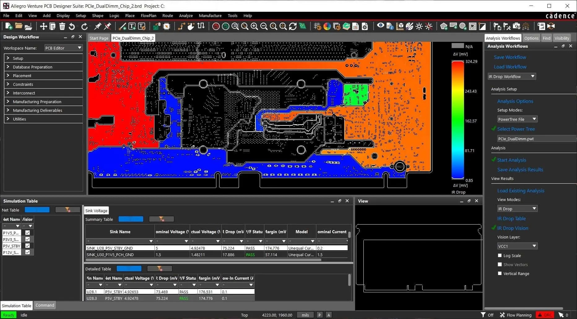
Evaluate your PDN and avoid instances of insufficient voltage to critical components with the IR Drop workflow in Cadence Allegro X.
Ground and Power Plane Construction
The construction of the ground and power plane is crucial. Large copper planes in a circuit board result in more surface area for heat dissipation, as they act as heat sinks. Therefore, making them as large as possible will help keep your board cooler. Connecting large planes to external layers of the board will create an even greater chance of transferring heat to the environment.
Thermal Vias
Thermal vias are additional holes placed in the board to intentionally dissipate heat. They can be especially useful for multi-layer boards with internal copper layers, providing a path for heat to flow out from the center of the board.
Thermal Standards for PCB Design
For cases with high AC and DC, other aspects of your PCB layout that need to be considered to produce thermally reliable boards are outlined in IPC, UL, and IEC standards for consumer and commercial products. For example, IPC compliance requires designing for current density in traces and spacing between conductors. Consult these standards to prevent excessive temperature rise in traces and components.
PCB Thermal Design and Analysis With Allegro X and Celsius Thermal Solver
Allegro X allows you to adhere to rules set in the PCB thermal design guide with thermal-aware design rules, and integration with thermal analysis tools.
Celsius Thermal Solver aids in performing detailed thermal simulations, considering all modes of heat transfer and the electrical-thermal interplay.
|
Tool and Feature |
How It Helps with PCB Thermal Design |
|
Allegro X Thermal-aware Design Rules |
Allows the definition of thermal constraints and rules within the design environment. Designers can set maximum temperatures for components, specify thermal vias, and enforce spacing rules to mitigate overheating. |
|
Allegro X Dynamic Current and Thermal Analysis |
Enables real-time analysis of current densities and associated thermal effects during the design process. This helps in identifying potential hotspots and overcurrent issues early, allowing for immediate corrective actions such as adjusting trace widths or rerouting. |
|
Allegro X Integration with Celsius |
Seamlessly integrates with thermal analysis tools like Celsius Thermal Solver. This integration enables designers to perform thermal simulations directly from the PCB layout, facilitating iterative design adjustments based on thermal performance. Enables the import of PCB designs for thermal analysis without data translation errors. |
|
Celsius Thermal Solver Electrothermal Co-simulation |
Performs simultaneous electrical and thermal simulations to capture the interplay between electrical performance and heat generation. This co-simulation helps in accurately predicting temperature rises due to electrical activity and in optimizing the design accordingly. |
|
Celsius Thermal Solver Multi-Physics Thermal Simulation |
Accounts for various modes of heat transfer—conduction, convection, and radiation—in complex PCB assemblies. This analysis ensures that all thermal effects are considered, leading to more reliable thermal management strategies. |
|
Celsius Thermal Solver Detailed Thermal Modeling |
Allows for the creation of detailed thermal models of components, PCBs, and entire systems. Accurate modeling helps in identifying thermal bottlenecks and assessing the effectiveness of thermal mitigation techniques like heat sinks, thermal vias, and airflow enhancements. |
|
Celsius Thermal Solver Automated Thermal Reporting |
Generates detailed thermal reports highlighting critical temperatures, heat fluxes, and thermal resistances. These reports aid in documenting compliance with thermal design standards and in communicating thermal performance to stakeholders. |
Effective PCB thermal design is essential for ensuring your circuit boards can withstand high temperatures and maintain reliable performance. Designers can leverage Cadence Allegro X to set design rules, analyze current densities, and integrate seamlessly with the Celsius Thermal Solver for comprehensive thermal simulations. Explore how Cadence's PCB Design and Analysis Software can improve your next project and learn more about Allegro X.
Leading electronics providers rely on Cadence products to optimize power, space, and energy needs for a wide variety of market applications. To learn more about our innovative solutions, talk to our team of experts or subscribe to our YouTube channel.