Comprehensive Microcontroller PCB Design Guidelines
Key Takeaways
-
Microcontroller Selection: Choose based on the project's processing needs, memory, and I/O requirements.
-
Power Supply Design: Use stable voltage regulators and decoupling capacitors to ensure consistent operation.
-
Programming and Bootloader: Ensure accessible programming interfaces like SWD or JTAG, and consider bootloader modes for firmware updates.

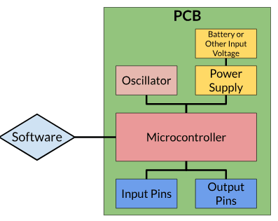
Basic block diagram of PCB with microcontroller.
Designing a PCB for a microcontroller is different from traditional PCB layouts due to the extra requirements for microcontroller selection, bootloader, and programming. A microcontroller (MCU) board is essentially a programmable circuit board that incorporates one or more microcontrollers.
These microcontrollers act as the "brains" of the board, integrating key components including CPUs, memory and and input/output peripherals. Microcontroller-based PCBs are typically used in embedded systems and devices, allowing them to execute software-driven tasks efficiently. Read on to learn about microcontroller PCB design guidelines.
Microcontroller PCB Design Guidelines Discussed
|
Design Step |
Description |
|
Design and Scope Preparation |
Define project requirements and select the appropriate microcontroller based on complexity and needs. |
|
Block Diagram |
Visualize the system architecture, including processing power, power, thermal management, and I/O needs. |
|
Selecting a Microcontroller |
Choose a microcontroller based on processing needs, type (AVR, PIC, ARM), memory, and peripherals. |
|
Memory Requirements |
Estimate flash memory and RAM needs for program storage and data handling. |
|
Peripherals and Interfaces |
Define required communication protocols and number of GPIO pins. |
|
Toolchain Selection |
Select a development environment with debugging, code completion, and simulation capabilities. |
|
Bootloader and Programming |
Consider bootloader modes and ensure accessible programming interfaces on the PCB. |
|
Power Supply Design |
Implement stable power management with voltage regulators, decoupling capacitors, and battery backup. |
|
Clock Circuit Design |
Choose internal or external oscillators based on timing accuracy needs. |
|
Schematic and Component Libraries |
Organize the design into manageable sections and ensure accurate footprints and libraries. |
|
Microcontroller Programming |
Select programming interface (SWD, JTAG, UART) and ensure accessible connectors. |
|
DFA and DFM Considerations |
Follow assembly rules for component placement and use DFA tools to optimize manufacturability. |
Design and Scope Preparation
The first step in microcontroller PCB design involves determining the appropriate controller type and identifying the components based on the project's requirements. The complexity of your project will dictate the kind of microcontroller you need and other I/O components. For example, a basic MCU with a few kilobytes of memory and a single I/O input might be enough for a simple timed function. However, more complex projects with intricate logic or multiple I/O channels will demand a more powerful microcontroller.
Selecting a Microcontroller
Choosing the right microcontroller is a critical step in developing embedded systems. The microcontroller will dictate the performance and capabilities of your design, so it’s essential to consider several factors carefully before making a decision.
The needs of your application should dictate your design. For simple control functions, such as managing basic timed tasks, an 8-bit microcontroller is typically sufficient. However, for more demanding tasks like digital signal processing, image recognition, or real-time data analysis, a 32-bit microcontroller with a higher clock speed and more advanced features will be necessary.
Microcontroller Types
Microcontrollers come in many varieties, and the right type depends heavily on the project’s specific requirements. Some common types include:
-
AVR MCU: Popular for small, low-power applications.
-
PIC MCU: Known for versatility and robustness in embedded systems.
-
ARM MCU: Favored for high-performance applications with a wide range of features.
-
8051 MCU: Older but still used in many applications due to its simplicity.
-
MSP MCU: Known for ultra-low-power applications.
When selecting an MCU, consider key specifications like bit rate (16, 32, or 64-bit), architecture (RISC or CISC), memory (on-chip or off-chip), and package type (e.g., SIP, DIP, QFP, BGA). ARM-based microcontrollers are the most widely used due to their scalability and strong manufacturer support.

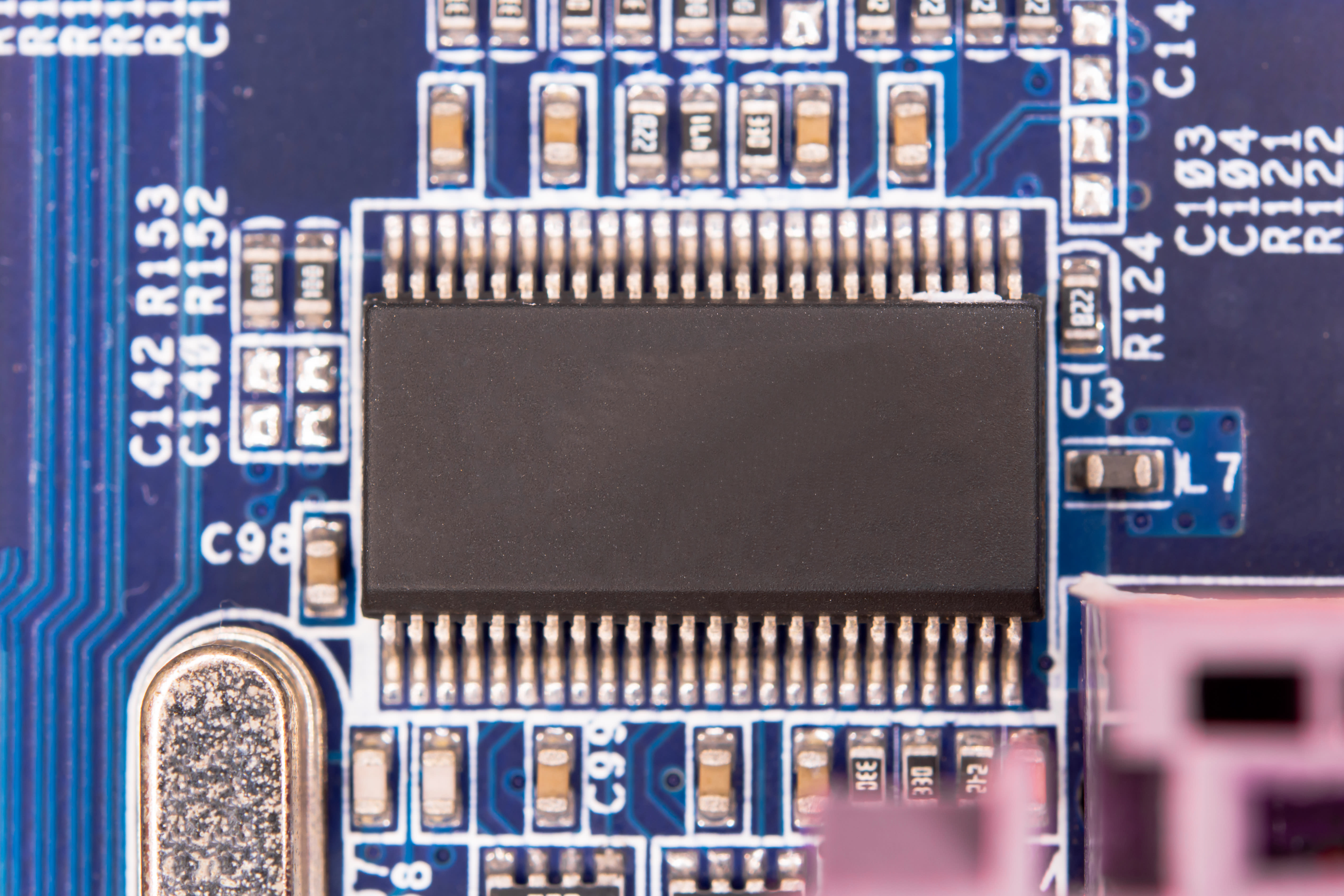
Microcontroller on a PCB.
Memory Requirements
-
Flash Memory: This is where your program code is stored, so it’s important to estimate the size of your firmware and ensure the microcontroller has enough flash memory to accommodate it.
-
RAM: Temporary data storage during operation is determined by the amount of RAM. Applications that involve handling complex data structures or need data buffering will require more RAM to ensure smooth functionality.
Peripherals and Interfaces
Identify which communication interfaces your project requires, such as UART, SPI, I2C, CAN, USB, or Ethernet. The number of GPIO (General-Purpose Input/Output) pins should also be considered, especially if your project involves controlling various sensors or devices. Additionally, determine if special functions like PWM outputs, ADC (Analog-to-Digital Converters), or DAC (Digital-to-Analog Converters) are needed for your design.
Importance of a Good Toolchain
A toolchain is a set of programming tools used together to create software or hardware solutions. Each tool in the chain performs a specific task, and together, they facilitate the entire development process.
A reliable toolchain is critical to the efficiency and success of your development process. Look for a development environment that offers Ease of use and features for debugging, code completion, and simulation capabilities.
Bootloader Information for PCB Design
Microcontrollers typically offer several boot modes, and understanding how to use the bootloader is essential for firmware updates and development.
-
In Bootloader Mode the microcontroller is able to receive new firmware over standard communication interfaces (such as UART, USB, or I2C) without needing a debugger. This mode is particularly useful for updating firmware in the field or when a debugger is unavailable. Bootloader mode supports multiple interfaces, allowing flexibility for firmware delivery.
-
In User Flash Mode the microcontroller will normally boot from the user flash memory, where the application code resides. This is the standard mode for running the firmware after it has been uploaded.
-
In System Memory Mode Some microcontrollers feature a dedicated system memory area that contains manufacturer-specific bootloader code. This allows the device to be programmed or reprogrammed through standard communication interfaces, providing a fallback option if other programming methods fail.
Power Supply for Microcontrollers
A stable power supply is important for the operation of a microcontroller, which uses on a digital clock and can sometimes have analog functions. Because microcontrollers are highly sensitive to voltage fluctuations, maintaining a consistent supply is critical. To achieve this, it's important to include bypass capacitors near the sensor pins and use power supply filtering to smooth out any noise or interference.
To provide the microcontroller with the correct operating voltage, use voltage regulators to step down higher input voltages, such as converting 5V from USB power to the 3.3V commonly required by many microcontrollers–whether they be a linear or switching regulator.
Power Supply Considerations
Reliable power management is essential for ensuring stable microcontroller operation.
-
Voltage Regulators: Use low-dropout regulators (LDOs) if the input voltage is higher than what the microcontroller requires, helping to maintain a consistent voltage level.
-
Power Supply Decoupling: Place bulk capacitors, such as 10µF or greater, near the power input to stabilize the supply and prevent voltage fluctuations.
-
Battery Backup: For applications that require uninterrupted operation, such as real-time clocks (RTC), design a battery backup circuit to ensure continuous power during main supply failures.
Clock Circuits
The clock circuit is another important part of microcontroller design, as it provides the timing necessary for the microcontroller’s operations. The choice of an internal or external oscillator depends on the accuracy and stability required by the application.
-
Internal oscillators are integrated into the microcontroller and are easy to use since they require no external components. They are sufficient for applications where timing precision is not critical. However, they tend to be less accurate and stable than external oscillators.
-
For applications requiring precise and stable timing, such as communication protocols or real-time clocks, an external crystal oscillator is preferred. Crystals provide higher accuracy and long-term stability, ensuring reliable performance in timing-critical operations. When using an external oscillator, ensure that load capacitors are placed close to the crystal to optimize its performance.
Schematic Section Design Guidelines
When designing a PCB, especially one that interfaces with other components or modules, following solid schematic design rules is critical. One key to this process is having access to a well-organized component library. Using cloud-based libraries can be extremely helpful, as they provide access to a wide range of up-to-date components. This enables you to easily pull verified parts for your design.
Begin your design by placing key active components, such as microcontrollers or ICs. If your circuit is large or complex, consider breaking it down into subcircuits. By organizing your design into smaller, manageable sections, you can join these subcircuits later, making the design process more straightforward. This also simplifies the creation of the Bill of Materials (BOM), as each section can be accounted for individually.
Footprints and Libraries
Whether you're using standard footprints or custom ones, footprints must match the physical layout specified in the component's datasheet to prevent assembly issues.
-
Use Verified Footprints: Standard footprints from well-known libraries are less likely to cause problems during manufacturing. If you're using custom footprints, verify them thoroughly against the component datasheet.
-
Maintain Accurate Libraries: Keeping your component libraries organized and up-to-date helps avoid mistakes in footprint selection and ensures a smoother production process.
-
See our last section for how OrCAD X can aid with these challenges.
Microcontroller PCB Layout Design Guidelines
Optimizing the PCB layout is crucial to reducing signal degradation caused by electromagnetic interference (EMI), especially in high-speed and high-power designs. By following established routing guidelines for high-speed or high-power signals, you can minimize losses and ensure reliable signal integrity. Proper routing techniques can help prevent issues that could impact the overall performance of the microcontroller and connected components.
ESD and EMI Protection
To safeguard your microcontroller from external interference and electrical surges, it’s important to implement robust ESD and EMI protection.
-
Input Protection: For input pins exposed to the environment, use series resistors and protection diodes to prevent damage from electrostatic discharge.
-
Filtering: High-frequency noise can disrupt signal quality, so incorporating capacitors and ferrite beads will help filter out unwanted interference.
-
Shielding: If your design involves sensitive components or traces, consider using shielding techniques to further protect against EMI.
For more information, see our pieces on filtering and shielding for more specific information.
Programming Pins and Communication Interface Routing
When designing your PCB, place the programming header—such as SWD or JTAG—in an easily accessible location, typically near the edge of the board. This placement simplifies access during the development and testing phases, making it easier to connect debugging tools.
-
Accessible Location: Position the programming header (SWD or JTAG) near the PCB edge to facilitate quick connection during debugging and programming.
-
Label the Pins: Make sure the programming pins are clearly labeled on the silkscreen, allowing for quick and correct identification of the debug header during testing and development.
-
Standard Pinout: Utilize a standard pinout (e.g., 2x5 1.27mm or 2x3 2.54mm headers) for the debug header. This ensures compatibility with common debugging tools and makes setup more straightforward.
Interface Selection and Connector Design
Select a programming interface based on the microcontroller and project needs: SWD for simplicity (e.g., STM32) or JTAG for complex debugging. Use a 20-pin JTAG for full access or a 10-pin SWD for compact designs. Ensure access to key signals like SWDIO, SWCLK, NRST, VDD, and GND.
Layout and Routing Considerations
Place the programming connector in an accessible location with short trace lengths for signal integrity. For communication lines (UART, USB, I2C), keep traces short and avoid interference. Route USB D+ and D- as a differential pair with controlled impedance for reliable performance.

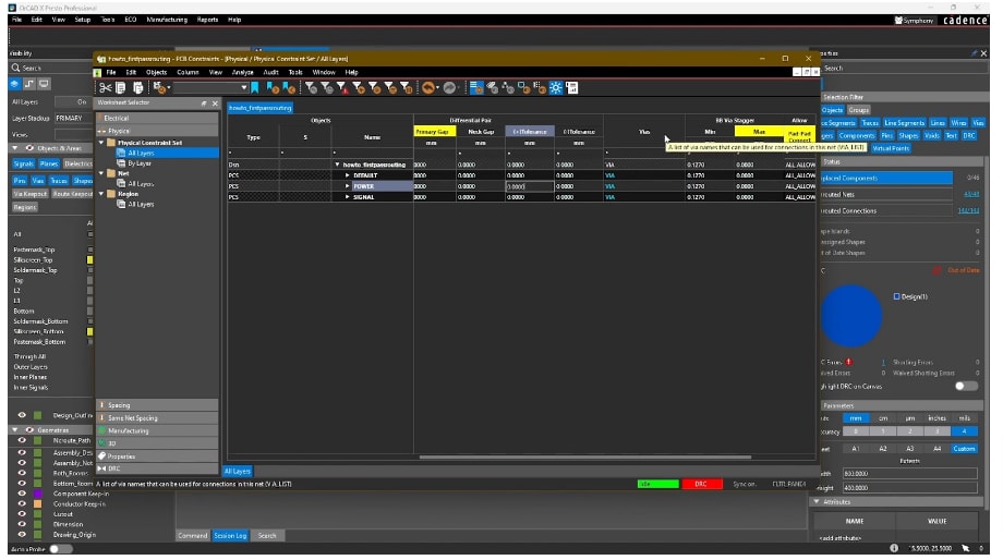
Setting physical constraints in the OrCAD X Constraint Manager
DFA and DFM With OrCAD X For Microcontroller PCB Design Guideline Adherence
OrCAD X streamlines microcontroller PCB design by enforcing DFA and DFM rules for optimized component placement, minimizing assembly errors. Real-time DRC checks detect violations early, while the advanced 3D engine ensures proper fit for rigid-flex designs. Integration with MCAD tools like SolidWorks enhances mechanical alignment, and Live BOM management provides up-to-date component availability and risk assessments. Footprint verification and easy access to test points further enhance design reliability and manufacturability.
|
OrCAD X Capability |
Description |
|
DFA and DFM Rules Enforcement |
- Ensures optimal component placement and spacing for manufacturability. |
|
Real-Time DRC (Design Rule Check) |
- Detects component placement violations during design. |
|
3D Visualization Engine |
- Provides real-time visualization of PCB layouts, including rigid-flex designs. |
|
MCAD-ECAD Integration |
- Collaborates seamlessly with tools like SolidWorks for mechanical alignment. |
|
Live BOM Management |
- Provides real-time insights into component availability and lifecycle status.. |
Cadence tools like OrCAD X offer powerful features to ensure you adhere to good microntroller pcb design guidelines. By integrating DFA and DFM rules, OrCAD ensures your PCBs are production-ready, minimizing errors and improving overall design quality. Explore how OrCAD can enhance your designs on the PCB Design and Analysis Software page and learn more about the capabilities of OrCAD X.
Leading electronics providers rely on Cadence products to optimize power, space, and energy needs for a wide variety of market applications. To learn more about our innovative solutions, talk to our team of experts or subscribe to our YouTube channel.