The Difference Between Regulated and Unregulated Power Supply in PCB Design
Key Takeaways
-
The difference between regulated and unregulated power supply in PCB design.
-
Power supply applications and what boards they should be used on.
-
Layout recommendations for PCB power supply design.
Circuit board design involves making a lot of choices to best satisfy the needs of the design that you are creating. One of the first of those choices is the type of power supply the circuit board will need, followed by how this circuitry should be laid out. There are many types of power supply circuits that you can work with, but first, you will need to understand the difference between regulated and unregulated power supply for the board.
The application of the board will determine the type of power that it needs. Although most boards are built with regulated power supplies, there are some applications that will allow for an unregulated supply instead. This article will start with a look at the difference between regulated and unregulated power supply designs and how you should choose between them. After that, we’ll look at some PCB design best practices for power supply layouts that can help you to make the right design choices for your next project.
What Is the Difference Between Regulated and Unregulated Power Supply?
Electronics typically require DC power of a specific voltage for their operation. While some devices will run off a battery or solar cell, most will use power supply circuitry built into the board to convert incoming AC power into DC. The goal of the power supply is to provide the expected DC voltage based on the given current. However, since power equals current times the voltage, any changes to one side of the equation will affect the other. For instance, if the load increases the current it is drawing, the voltage will decrease proportionally so the overall amount of energy remains the same. Most power supply circuitry will include a voltage regulator to maintain the same voltage level, but for some devices, voltage regulation may not be required.
Regulated Power Supply
The majority of electronics today require a steady voltage level for their operation. Changes in voltage can degrade the performance of the rest of the circuitry or damage it. To prevent this, a voltage regulator is used, which evens out the amount of ripple voltage in the output of the power supply. Ripple voltage is AC voltage that has been mixed in with the DC output voltage. The voltage regulator provides a smooth, clean, and steady supply of DC voltage regardless of any load or input fluctuations.
Unregulated Power Supply
For those devices that don’t require a steady voltage to operate, the voltage regulator can be omitted from the power supply circuitry. The majority of the power supply circuitry will still be the same, but its output voltage won’t be regulated and any changes to the AC input or the load will affect the DC output voltage. Filter capacitors may be used to help smooth out the ripple voltage, but they will not be effective against high-frequency noise coming from the AC input.
There are some advantages to unregulated power supplies, which should be considered when deciding what type of power to design into your circuit board. Without the voltage regulation, the number of components in the power supply circuitry is reduced, making for a simpler and less expensive design to build. If your power requirements allow it, an unregulated power supply can be an effective low-cost solution. Next, we’ll take a look at some of the applications where regulated and unregulated power supplies are used.
Voltage regulators used in PCB power supply designs
The Applications of Regulated and Unregulated Power in PCB Design
As we have discussed, choosing between a regulated and unregulated power supply depends on the requirements of your circuit board. If the power specifications demand steady voltages for devices that are sensitive to voltage changes, then you should look at using a regulated power supply. However, if the circuit board can tolerate varying voltages, then an unregulated power supply can help lower your component and manufacturing costs as well as free up more room on the board. In some cases, the filtering effects of capacitors can smooth out the ripple voltages enough to justify using an unregulated supply over a more expensive regulated version. Here are some of the applications that require regulated power and those that don’t.
As you can see, computerized products require the stability of regulated power supplies while electro-mechanical devices can tolerate some fluctuations. Once you’ve made your choice and incorporated the power supply into your design, the next step is to lay out the supply on the board. Next, we’ll look at some of the recommended best practices for power supply design on a PCB.
A tight placement of parts is essential when laying out power components
PCB Layout Requirements for Power Supply Design
Laying out the power supply circuitry on a printed circuit board, as illustrated in the picture above, will follow the same basic procedures as laying out the rest of the board. You will want to work from the schematic to plan the layout and follow all of the DFM rules that apply to your design. You will also want to make sure that your parts are correctly synchronized between the schematic and the layout database so you are working with the correct PCB footprints. However, there are some additional layout considerations for power supplies that you must keep in mind as your work.
Component Placement
One important consideration with power supply circuitry is dealing with the heat that these parts will create. You should separate different power supply circuits from each other to prevent an overload of heat. Position the parts where they will benefit most from any airflow across the surface of the board. The components within the power supply circuit should be placed as close together as possible and on the same side of the board to minimize the routing and eliminate the need for vias. This will reduce the possibility of creating impedance in the circuitry. Start with the main components of the power supply, such as a converter, and continue outward from that with the main capacitors and inductors. The closer the parts are to each other, the less EMI they will be likely to generate.
Trace Routing
It is important to keep your traces as short and direct as possible. This shouldn’t be a problem if you have placed the components for the most optimal routing. The main current-carrying traces should be as wide as possible to help minimize any inductance. It also helps to route corners with 45° angles or rounded corners. Do not route non-power supply traces through this area to avoid contaminating them with power supply noise. Remember, keep the connections as direct as possible and do not route power supply traces through the board to other layers. Keep the routing on the surface of the board with the components.
Ground Planes
For the best performance of the power supply circuitry, a solid ground plane on the next board layer is recommended over using routed ground traces. A ground plane will help with both power integrity and thermal dissipation. It is essential to understand the current flows of your power supply on the ground plane and avoid routing any other non-power supply traces in this area. The ground plane under the power supply can be walled off to isolate it from the rest of the common ground, but will still have to connect at one point on the plane. Make sure that a designated area on a ground plane for the power supply completely encompasses all of its components.
Thermal Concerns
Although vias shouldn’t be used for power supply routing, vias have to be used to connect the ground to an internal plane. These vias will also help dissipate heat down into and through the ground plane. As we stated earlier, leverage the airflow across the board for cooling, and don’t hesitate to use additional cooling devices such as heat sinks, thermal paste, and fans if necessary. With the need to control so many aspects of the layout for power integrity, EMI control, and thermal relief, it is important to follow strict layout rules and constraints. Here is where your design tools can offer some help.
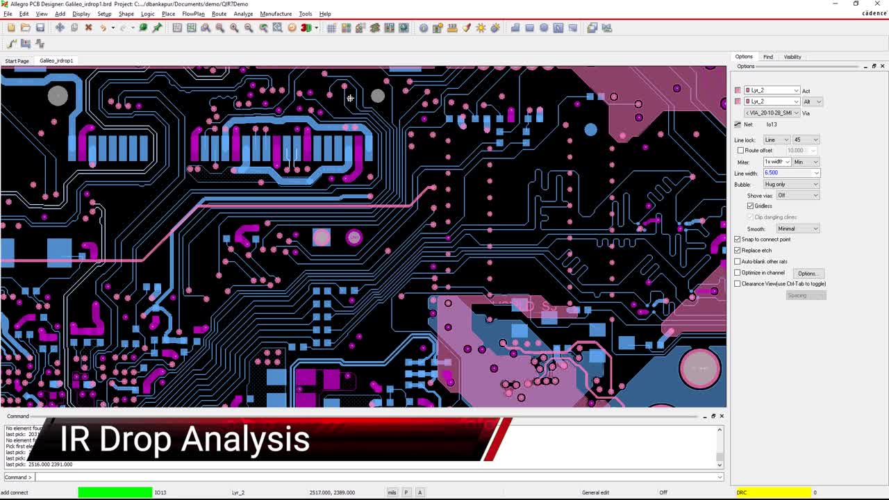
The Constraint Manager in Cadence Allegro’s PCB Editor can be fine-tuned for power supply circuitry
How Your PCB Design Tools Can Help
At this point, we’ve explored the difference between regulated and unregulated power supplies and we’ve seen the importance of component placement, trace widths, and ground plane development in power supply designs on printed circuit boards. PCB design CAD tools have numerous features to help designers with their layouts, starting with rules and constraints.
In the picture above, you can see the Constraint Manager that comes with Cadence’s Allegro PCB Editor. This tool allows designs to specify trace widths and clearances for different nets or classes of nets as well as components. Notice the Constraint Manager’s settings for via clearances to different net objects in the design. By managing these settings, design engineers can place and route their layouts with the tightest clearances for best performance while ensuring optimum manufacturability.
For more information on power supply design and configuring the power delivery network of your PCB design, take a look at this E-book from Cadence on PDN design. Leading electronics providers rely on Cadence products to optimize power, space, and energy needs for a wide variety of market applications. If you’re looking to learn more about our innovative solutions, talk to our team of experts or subscribe to our YouTube channel.