PCB Panelization Guidelines for Layout Considerations
Key Takeaways
-
The basics of manufacturing panels.
-
Fundamental PCB panelization guidelines.
-
PCB panel clearances and other tips.
Small circuit boards need to follow PCB panelization guidelines for manufacturing
Long before scanners, laser printers, and photocopiers made document reproduction easy, documents had to be reproduced manually. Then, in 1803, the polygraph duplicating machine—a system that mechanically mimics what is being written using pen and ink on a second document—was patented. The inventors realized that if you could produce two documents with the effort to write just one, your work would be twice as efficient.
Manufacturing panels for printed circuit boards accomplish the same principle as those early polygraph duplicators by simultaneously creating multiple copies of a circuit board. However, there are many other benefits to using manufacturing panels for both fabrication and assembly. To ensure that the benefits of these panels are maximized, PCB designers need to understand how best to lay out circuit board designs. Here are some PCB panelization guidelines that can help.
Manufacturing Panels for PCB Production
A printed circuit board manufacturing panel is designed to help automate the fabrication and assembly process. The panel will have the same materials and board layer stackup configuration as the board, and its size and shape will be contoured to the different manufacturing processes required to build the board. Although 18 X 24 inches is a standard size for many panels, they can be built to different sizes depending on the needs of the PCBs they contain.
The panel itself will contain one or more instances of the printed circuit board design. The smaller the board, the more instances can be placed within the panel, and the manufacturer will arrange the images to make the best use of the space. Here are some other benefits of using a panel for PCB manufacturing:
- Small boards can be difficult to handle; panelizing them makes manufacturing more efficient and reduces defects.
- Panelizing boards is a more cost-effective method of production than changing manufacturing processes to accept smaller boards.
- Panels can contain the necessary fiducials, alignment holes, and other manufacturing creature requirements instead of fitting them into a smaller board.
- Building multiple boards at one time in a panel reduces overall manufacturing costs.
Building a printed circuit board in a panel is usually the best option, and your manufacturer will be able to show you exactly how it will benefit your specific project. However, there are some panel related concerns that layout designers need to be aware of:
- Circuit boards will eventually have to be removed or depanelized from their panels after manufacturing is completed. Manufacturers will incorporate special features into the panel design to facilitate this depanelization. The layout designer must understand the requirements for these features and provide the necessary clearances in the PCB design to prevent damage to the components and circuitry.
- The circuit board designer needs to provide clearances for other panel requirements as well. These include how far components can stick out over the side of the board, as you can see illustrated below, or if stiffener bars will need to be added. If this isn’t done in the layout, then the panel designer will have to work around these problems, adding time and complexity to their process.
- The PCB layout needs to be optimized for manufacturing according to how it will be laid out in the panel. For example, SMT components must be aligned in certain orientations for wave soldering. To maintain this preferred component alignment, the panel designer may be restricted from the most efficient arrangement of boards within the panel.
Next, we’ll look a little closer into the special features that are added to panels to help depanelize the boards.
Some components extend over the edge of the board, which must be accounted for in the panel
Demystifying Depanelization
A contract manufacturer usually creates manufacturing panels for printed circuit board designs. These people create panels all the time and are most familiar with their manufacturing processes and the processes of their fabrication partners. Once the panel database has been created, its data is sent to the fabricator to build the raw circuit boards. Here, the panels help the fabrication process by giving the equipment more material to guide, hold, and otherwise work with.
Once the raw boards are complete, they are sent back to the PCB CM who assembles the parts to the boards while still in their panels. At this point, the individual PCBs must be separated from their panels, and the manufacturer will rely on some special features designed into the panel to help this process. Circuit boards are broken out of their panels either by cutting along a pre-cut channel, called a “V-groove,” or by removing little breakout tabs holding a pre-routed board in place.
Tab-Routing or Breakout Tabs
For panels using breakout tabs, a router is used to mill around the board outlines in the panel, except for strategically placed tabs, which are broken out for depanelization of the boards. Breakout tabs offer more flexibility than V-grooves when the boards have complex shapes or overhanging components such as connectors. Each tab typically has between three and five small holes drilled into it. These holes have a 0.020-inch diameter and are spaced 0.030 inches apart. They make it easier to break out the tabs to depanelize the boards.
V-Grooves
For circuit boards that have long, straight sides and no overhanging parts, V-groove panelization is used. On both the top and bottom of the board, a triangular saw is used to cut about a third of the way through the board material, leaving a thin strip of material to hold the board in the panel. When the board is depanelized, it can be separated out with simple tools. As shown in the picture below, cutting V-grooves in a panel is a much faster process than creating breakout tabs. It takes very little time to pass the boards through the saw, and V-grooves take much less space than routing the boards out for breakout tabs.
Now that we’ve explored the different aspects of a PCB manufacturing panel, let’s take a look at some of the layout guidelines PCB designers need to know for successful panelization.
A panel of circuit boards with a V-groove added to facilitate depanelization
PCB Panelization Guidelines for Layout
The goal during manufacturing is to reduce the labor, materials, and chance of errors during production while improving the precision and quality of the final product. This is true in PCB manufacturing as well, and to help with this goal, PCB designers need to understand how their layout decisions will impact the panel and its manufacturing. For instance, making alterations to the board’s shape or reducing its size may help make the panel more efficient for manufacturing. Another example of a PCB panelization guideline is to possibly design other system boards using the same layer stackup configuration so that the different boards can be panelized together. For large boards with unusual shapes, including a smaller-sized board on the same panel helps reduce manufacturing costs.
The most critical area of panel requirements for PCB layout is to observe the clearances. Sensitive areas of circuitry and components need to be held back from the board edge to protect them during depanelization. Additionally, breakout tabs and V-grooves both have unique clearances that have to be held. As a reminder, these are just PCB panelization guidelines; you should confirm actual clearances with your PCB CM, as they tend to vary between manufacturers.
Breakout Tabs:
- To prevent any possibility of damage from splinters when the boards are broken out, components should be kept back a minimum of 0.125 inches from a tab. Taller components, like electrolytic capacitors, should be kept back 0.250 inches from a tab.
- While copper traces and planes can be very close to the edge of a board (0.005 inches), they should be kept back 0.125 inches from where a tab will be located.
- Make sure that there is enough room for the number of tabs necessary to support the board during its manufacturing operations.
- Pay attention to sensitive areas of circuitry on the board that could be more susceptible to the stress put on the board with a breakout tab.
V-Grooves:
- Keep components back 0.050 from the edge of the board if it is to be cut with a V-groove.
- Taller components should be kept back 0.125 inches from the board edge to avoid interference from the cutting tools.
- Components with large solder pads should also be given more clearance to avoid any chance of their solder joints experiencing stress fractures during depanelization.
- Copper traces and planes should be kept back 0.020 inches from the board edge.
Each manufacturer will probably have panel requirements that differ slightly from each other, and these clearance values should be checked with your own PCB CM. Here are some other panel details to consider during PCB layout:
- Make sure to understand what depanelization method (breakout tabs or V-grooves) will be used before you set up your board edge clearances.
- Find out which way wave soldered boards will be arranged in the panel to place SMT discretes accordingly for the wave.
- Make sure to specify overhanging component outlines in your drawings so that the manufacturer will create the panel accordingly.
- Large components may cause a weight imbalance for the panel, especially if there are large concentrations of them. These may force the manufacturer to use stiffener bars or other panel support devices, which may require component placement keep-out zones in your layout.
- Thin circuit boards may also sag in the panel if they are large enough. This too could require braces or pallets to support the board during manufacturing, which, in turn, could affect your component placement.
Ultimately, the best advice is to work ahead with your contract manufacturer to ensure that you are both designing the board to be fully manufacturable. There are other areas of manufacturability in your layout that need to be observed too, and fortunately, your design tools can be a big help with these.
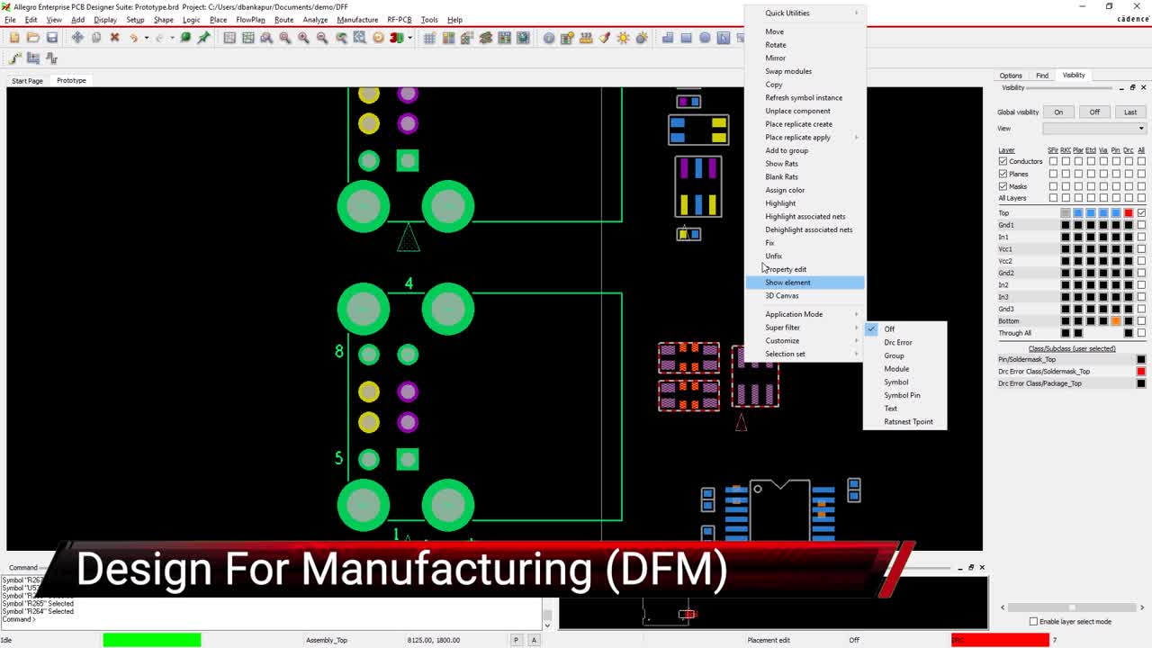
The Design for Assembly package spacing rules being set up in Cadence’s Allegro PCB Editor
PCB Layout Features to Help With Manufacturing
As we have seen, clearances are very important in the creation of a good PCB manufacturing panel. However, these clearances are critical for manufacturability across the entire board. This is where advanced PCB design tools can help with features like design rules and constraint systems to keep your clearances correct throughout the design. As you can see above, the Constraint Manager in Cadence’s Allegro PCB Editor can easily be set up to manage component to component clearances. Additionally, classes of components can be created, making your job all that much easier.
Allegro also gives you many other design constraints that can be set and a host of other features and tools. You can use the 3D canvas to verify the clearances to other objects and system boards, and the manufacturability checks (as shown in the video at the top of this article). No matter what your needs, Cadence has the tool features to support them.
To learn more about designing for manufacturability or DFM, take a look at this E-book.
Leading electronics providers rely on Cadence products to optimize power, space, and energy needs for a wide variety of market applications. To learn more about our innovative solutions, subscribe to our newsletter or our YouTube channel.