Matched Terminations Help Avoid Impedance Issues
Until the mid-19th century, personal communication—no matter how important—took days and sometimes months. But…innovation—albeit labeled as “impracticable or crazy” persisted.
The possibility of coupling electricity with a device that could send messages over long distances seemed incredibly ludicrous until the invention of the telegraph. Even then, transmitting a message required someone stationed at a sending office and another someone stationed at a receiving office hunched over a telegraph key that completed an electrical circuit. Many times, multiple sending and receiving offices and multiple operators helped transfer messages over two wires.
Poor quality signal lines and inefficient batteries functioning as power supplies impeded electric currents. Privacy was not an issue because no message was private. Tap…tap…tap-tap-tap…tap. Every receiving station required operators who could translate Morse Code into an understandable message. Current provided the power needed to move an indicator needle and the buzzer that allowed an operator to hear the message.
We accomplish the same tasks with our latest technologies but with a much smoother, more private, and faster way. However, some of the same limiting factors still exist. The characteristics of a wire carrying an electrical signal establish the finite speed of the signal as it travels through a wire. Connecting high speed signals to a long transmission line can introduce delays equal to the signal rise time. Every transmission line offers resistance, inductance, and capacitance. And, every transmission line remains susceptible to reflections and ringing.
You Need Time for Reflection
When we work with high-speed digital circuits, propagation delays occur. From a circuit perspective, the delays can seem to imitate signal transition times. Rather than treat traces as perfect conductors that have zero delays, we should treat the traces as transmission lines. When looking at the conductors from the transmission line perspective, signal changes occur after an output changes state.
Placing two conductors in parallel on your PCB creates a simple transmission line. If we could have traces with an infinite length and instantaneously placed a voltage source across the trace pair, current flow would create a voltage wave that happily travels along the pair. Unfortunately, infinite length PCB traces only exist in theory but not in practice.
Instead, our traces—working as transmission lines—have a finite length. Placing a voltage across the pairs causes current to flow. Kirchoff tells us that if we terminate the traces with any value but the value of the characteristic impedance, a voltage wave will propagate back down the line and meet the original voltage wave. Although an instant friendship could occur from this meeting, things can go wrong. A reflected voltage wave that has the opposite polarity will cancel the original wave. In contrast, a reflected voltage wave that has the same polarity will add to the original wave.
A reflection coefficient (ρ) determines the amplitude of the reflected wave. The value of the coefficient equals the termination impedance (Zterm) at the end of the line minus the characteristic impedance (Z0) divided by the termination impedance plus the characteristic impedance. In equation form, the reflection coefficient appears as:
ρ = Zterm – Z0 / Zterm + Z0
Reflections can happen whenever the impedance of the transmission line changes along its length. A large variety of factors—such as stubs, vias, connectors, component packages, and mismatched drivers and loads—can change the impedance. As the signals reflect back and forth, another phenomenon called ringing occurs at the load. The oscillations inherent with ringing can cause false triggers and noise while reducing the receiver range.
Ensuring proper signal integrity in a design can be a tremendous pain if not checked consistently.
The optimal transfer of energy for traces exists when the impedance of the source equals the impedance of the trace and the impedance of the load. Using a resistance equal to the characteristic impedance of the transmission line to terminate the line allows us to avoid reflections. By terminating the traces with the characteristic impedance, we match both ends of the transmission line. The terminating resistor equalizes the impedances.
Ringing in My Ears Bothers Me
You can stop reflection and ringing in your PCB design by keeping traces electrically short—or no longer than one-third the rise time of the edge of the signal. With this approach, the rising or falling edge of the original signal envelops and overwhelms any reflected signal.
If your PCB design cannot achieve electrical short traces, you can use simulations found within your PCB design software to find the amount of source impedance needed to match the trace and the load. Your design software provides the tools for selecting a terminating resistor value that connects near the source or the load and the design rules that specify the methods used for matching the impedances. The termination method that you select depends on component footprints, trace routing, and the effective operating frequency of the circuit. The Effective Operating Frequency shows as:
Signal Frequency (GHz) = 0.35 / Signal Transition Time (nSec)
Try These Amazing Methods!
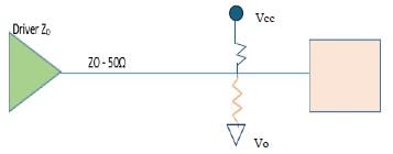
Impedance matching eliminates the data errors caused signal degradation, reflections, and line noise. With that in mind, let’s take another look at the need for trace termination. The common methods used for achieving matched termination include series, parallel, Thevenin, and AC termination. Using a clock driver as an example, series termination adds a terminating resistor at the output of the driver. The addition of the resistor matches the source and trace impedances while increasing the impedance at the line source.
Applying series termination accomplishes several things. The edge rate of the driver decreases and signal quality improves through the reduction of line noise and electromagnetic interference. However, because series termination does not terminate the load, a series-terminated trace only dampens ringing but does not stop reflections. Using series termination also slows the rise and fall time of the signal. Because of this last factor, series termination works well for single and dual transmission but not for distributed loads.
Again using a clock driver as an example, parallel termination places a single resistor at the load—rather than at the source—end of the trace. With this method, the terminating resistor value matches the values of load and line impedances. Placing the resistor at the load end prevents reflection by absorbing and dissipating energy.
As with parallel termination, Thevenin termination prevents signal reflection from the load end. The Thevenin method places a parallel combination of resistors at the load end that match the load and trace impedances. This configuration balances high and low logic levels from the integrated circuit.
Used for cables, backplanes, and distributed loads, the final type of matched termination method—called AC termination—uses a high-pass filter to terminate the load end. The AC termination method relies on an RC time constant that remains greater than the round-trip propagation time of the signal. Because the capacitor blocks low-frequency noise, it reduces quiescent power dissipation.
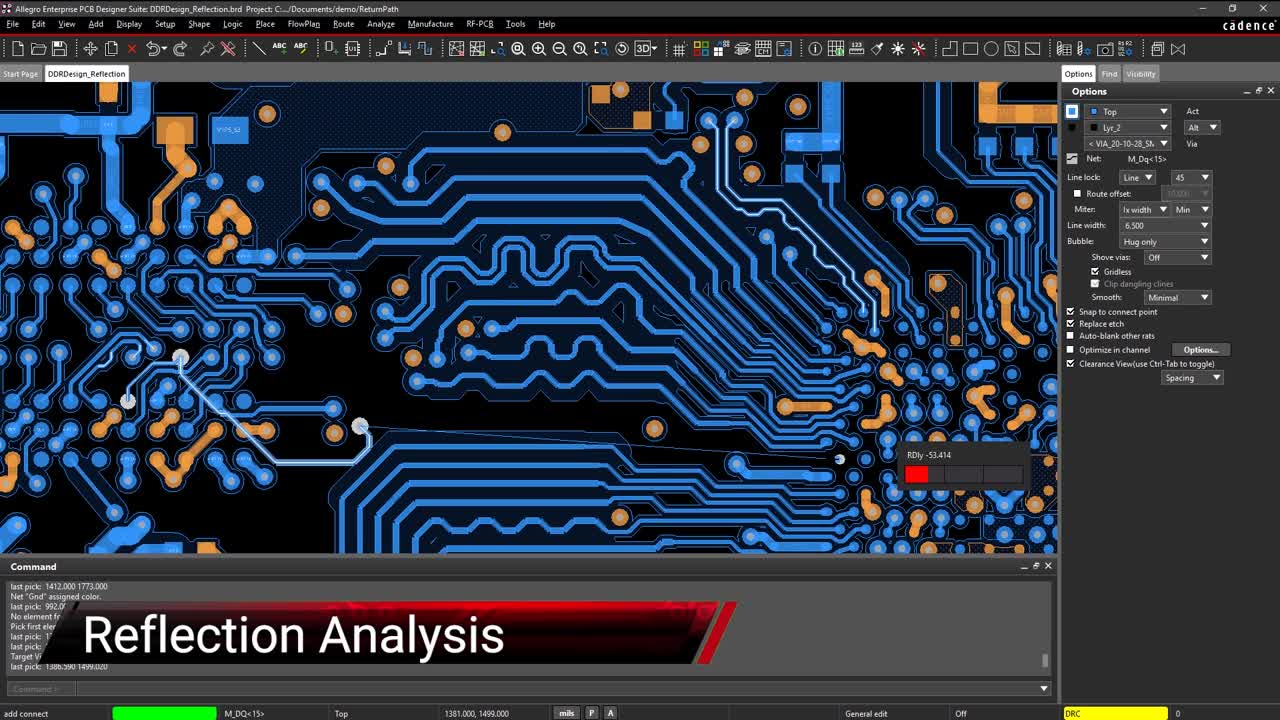
Cadence not only has the suite of design and analysis tools built with you and your team’s needs in mind, but also has the layout capacity to make any signal and impedance difficulties easy. Allegro PCB Designer comes with an advanced DRC engine capable of planning for any impedance challenge, as well as having augmentations for signal integrity analysis and transitions seamlessly to post-layout signal analysis.
If you’re looking to learn more about how Cadence has the solution for you, talk to us and our team of experts.