09 - Appendix A: Retaining Electrical Constraints at Net Level
Overview
When an Xnet is created, all the electrical constraints on the nets that form the Xnet are moved from the nets to the Xnet. If the same electrical constraints exist on more than one of the nets comprising the Xnet, pre-defined rules determine how these constraints are combined to form a single constraint which is then added to the Xnet.
The electrical constraints are checked at the Xnet level rather than the net level. For example, you change or delete a signal model that is assigned to a component and it results in the destruction of the existing Xnet. In such a case, the electrical constraints assigned to the Xnet being destroyed are moved to each of the nets in the Xnet.
You can retain electrical constraints at the net level. This feature lets you optionally disable the process of moving electrical constraints from member nets to the owner Xnets when an Xnet is created and destroyed. You can control when to check a constraint at the net level or at the Xnet level. In essence, this feature helps you decide whether an electrical constraint continues to reside on the net or be moved to the Xnet it is assigned.
The option to retain electrical constraints at the net level is disabled, by default, which means that the constraints are moved to the nets comprising the Xnet. You can opt to retain electrical constraints at net level using one of the following two methods:
- Setting CPM Directive
- Defining Allegro Environment Variable
Setting CPM Directive
Follow these steps tp set the CPM directive:
- Open the .cpm file.
- In the GLOBAL section, add the following directive:
RETAIN_ELECTRICAL_CONSTRAINTS_ON_NETS 'YES'
This indicates that the option is turned on. A value of NO or the absence of this directive in the .cpm file indicates that the option is turned off.
This value is applicable to any new logic design created using Allegro Design Entry HDL. It is also applicable to any new board design where the editor has been started with the -proj command line option that defines a .cpm file.
Defining Allegro Environment Variable
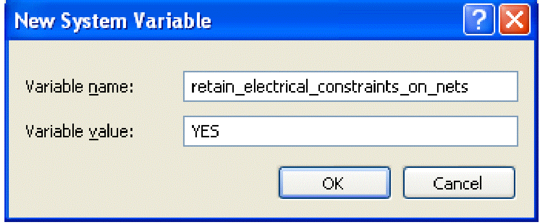
- Set the retain_electrical_constraints_on_nets environment variable:

This affects the new designs created by a layout editor.
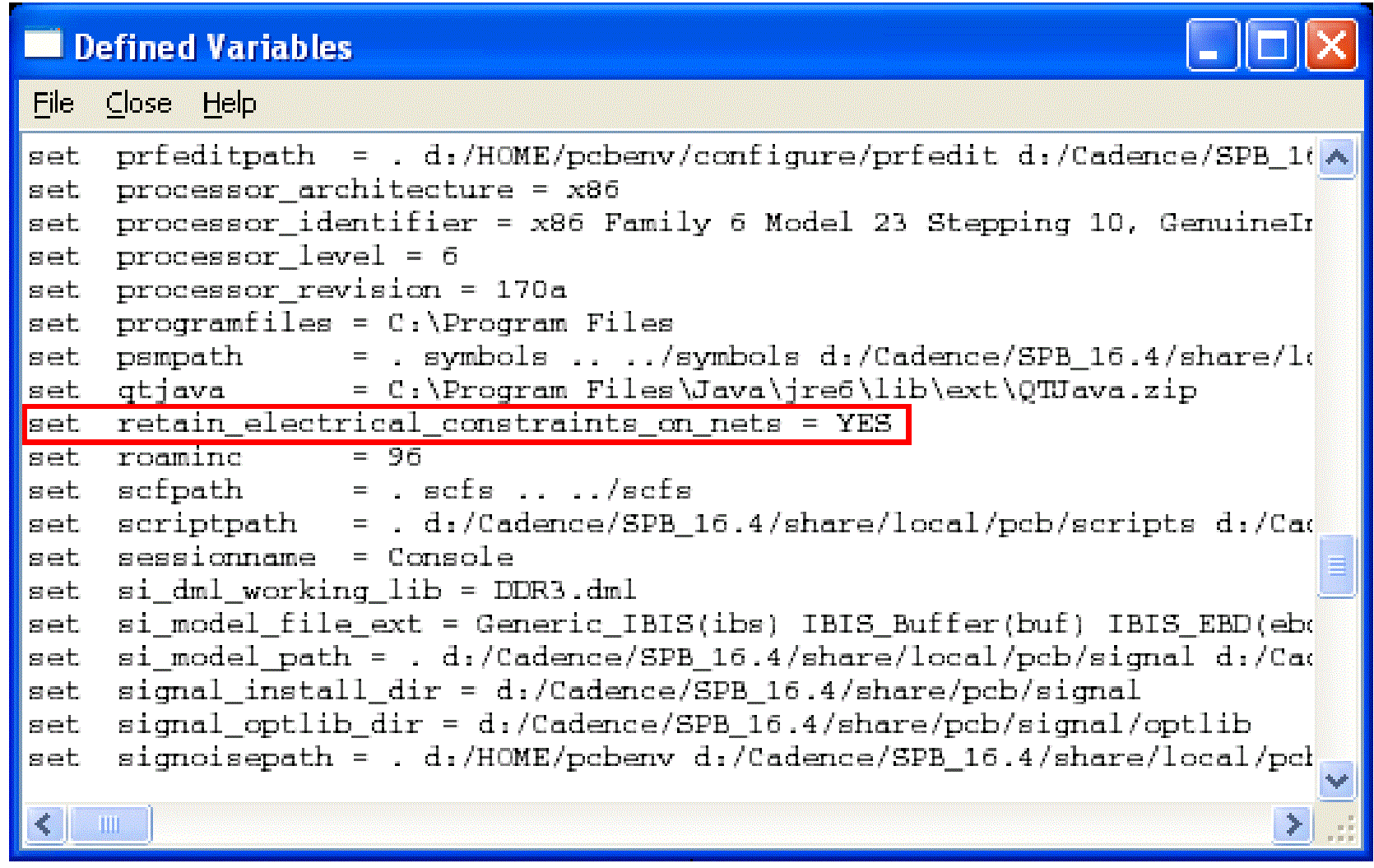
Confirm if the variable has been set, by choosing Tools – Utilities – Variables in PCB Editor.

When starting a new logic design, only the CPM directive is checked. When starting a new board design, first the CPM directive is checked. If it is not found, the environment variable is checked. If none of these options is found, the directive is assumed to be off and there is no entry in the .dcf file.
Use this directive with extreme caution, because after you set the directive either in the .cpm file or in the env file, it is written in the database and is locked. Now the design will always manage the constraints at the net level. You cannot revert the design to its original state by removing the directive. To revert the design, the databases needs to be edited and all Xnet constraints need to be checked.
Without the retain electrical constraints at net level option

With the retain electrical constraints at net level option

Front-to-Back Flow
The retain_electrical_constraints_on_nets environment variable is only processed in the front-to-back (F2B) flow for new designs. When a board is created with the -proj command line option, the new board is created with the retain electrical constraints at net level option as defined in the CPM file.
Similarly, if the corresponding environment variable is specified, it is processed for the new design. If the option differs between front end and back end for an existing design, the F2B flow fails. You need to update either the schematic or the layout before you re-run the F2B flow.
With the Retain electrical constraints at net level option on, If the net is a member of an Xnet both the net level constraints and the Xnet level constraints are listed.
Back-to-Front Flow
The retain_electrical_constraints_on_nets environment variable is not processed in the back-to-front (B2F) flow. If the option setting differs between front end and back end for an existing design, the B2F flow fails. You need to update either the schematic or the layout before you re-run the B2F flow.
If you have any questions or comments about the OrCAD X platform, click on the link below.
Contact Us