05 - Constraint Analysis
Overview
Allegro Constraint Manager analyzes the constraints in your design using two methods:
- Design Rule Checks
Real-time design rule checks are made on objects constrained in the Routing worksheets. Results are returned to the worksheet cells in focus by comparing changes in the layout, such as moving a part, against the constraint limits that you specified for these objects.
As design rule violations are found, Constraint Manager colors the corresponding worksheets cells in red. Additionally, bow tie markers appear on offending objects in the layout. - Simulated Analysis
Simulated analysis is made on objects constrained in the Signal Integrity and Timing worksheets in the Electrical domain.
Analyzed results are returned to the worksheet cells in focus by comparing computations (the actual) against the constraint limits that you specified for these objects. The actual, and the difference between the actual and the set constraint limit (the margin) are returned.The analysis engine computes a value (actual) and compares this to the value specified in the CSet. The difference between the analysis value and the specified constraint value is the margin. Both actuals and margins are returned to the cells in the appropriate worksheets.
The same color scheme is used for both analyzed results and design rule checks.
View Worksheet Cells and Objects
As the complexity of the design increases, the number of objects in the design also increases, and the number of CSets associated with those objects increases as a result. This can lead to a high degree of congestion in your worksheets. Constraint Manager lets you change the view of constraints, so that you can change your focus as you work.
The following table lists the various tasks you can perform within Constraint Manager, along with the corresponding steps.
| Task | Related Commands | Actions |
|
Locating an object, a result, or a CSet |
Edit – Find |
Finds the specified object. You can filter on the following:
You can click Find Next (or F3) to locate the next occurrence. |
|
Edit – Go to source |
Locates the parent object that owns the inherited ECSet of the selected child object. For example, if you select a child object, such as a bit in a bus, its constraints are inherited from a CSet that is associated with the parent object, in this case the bus. |
|
|
View – Options – Row Numbers |
Enables row numbering in the worksheets. |
|
|
Objects – Filter |
Selectively displays or hides the following objects in the worksheets:
|
|
|
Controlling the worksheet or object hierarchy |
Objects – Expand/Collapse (or use the [+] and [-] controls) |
Expands or collapses the worksheet hierarchy in the worksheet selector or the object hierarchy in the worksheets. Worst-case analysis results on collapsed (hidden) objects are rolled up to the expanded object. This notification lets you work at any level in the object hierarchy. |
|
View – Show All Rows |
Expands or collapses all rows in all worksheets. |
|
|
Working in columns |
Column – Sort (or double-click the column head) |
Reverses the ordering of objects or constraint values in a column. |
|
View – |
Hides columns in a worksheet so you can focus on a single, or a few, columns. Otherwise, you may have to scroll horizontally to access an out-of-view column. |
|
|
Resize |
Resizes column width. Grab a column border and drag. |
|
|
Comparing cells |
Window – Tile |
Compares the cells of two or more different worksheets. You may have to scroll to view the desired cells. |
|
Window – |
Compares cells in the same worksheet. Constraint Manager opens the same worksheet in a different window. You can scroll to different cell views while making concurrent edits in the same worksheet. |
|
|
Analyzing DRC-Based Constraints |
Setup – Constraints – Modes |
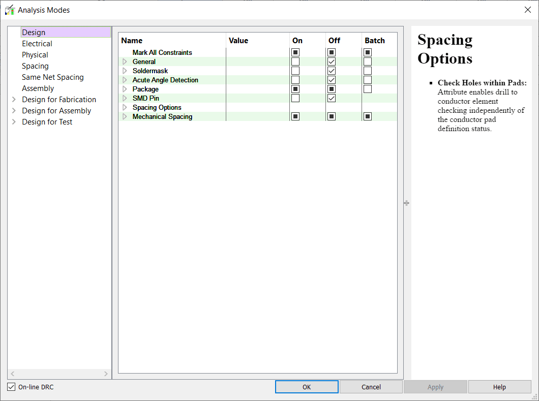
You control design rule checks with the domain tabs of the Analysis Modes dialog box. Alternatively, you can specify analysis settings, DRC modes, and desired reports from a single dialog box. |
DRC Constraint Modes
Use the Analysis Modes dialog box to control which DRCs to run. When the layout changes, an enabled design rule check is triggered.
Analysis Modes dialog box

Analyzing Simulation-Based Constraints
Certain constraints in the Electrical Domain (Signal Integrity and Timing) require the simulation to compute actual values. When the actual value is analyzed and returned to a worksheet cell, it is compared with the specified constraint value that is associated with the object being analyzed. The difference is calculated and displayed in the Margin column.
To analyze simulation-based constraints, Constraint Manager must be run with PCB Editor or APD.
Follow these steps to analyze simulation-based constraints:
- Configure the analysis engine (Analyze – Settings).
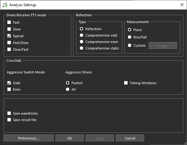
In the Analysis Settings dialog box, you specify the type of simulation, whether to use crosstalk timing windows, and the type of stimulus.
Alternatively, you can specify analysis settings, DRC modes, and desired reports from a single dialog box (Tools – Report).
You can click Preferences to specify buffer information (in the Analysis Preferences dialog box). You can also choose to save a waveform for each analysis; waveforms can subsequently be viewed in SigWave (choose Tools – SigWave). - Initiate analysis (Analyze – Analyze) on an object.
Creating Simulation-Based Custom Stimulus
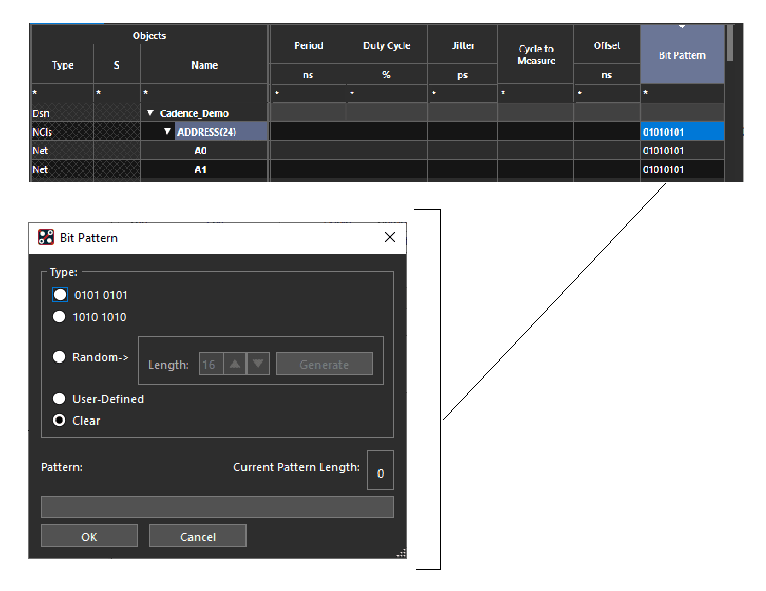
In addition to capturing custom stimulus in a SigXplorer topology file and importing it into Constraint Manager, you can create your own stimulus patterns directly in the Electrical Properties worksheet in the Signal Integrity workbook (Electrical Domain). Custom Stimulus is associated with Custom Measurements.

- Double-click in the Bit Pattern cell to invoke the editor.
The Bit Pattern dialog box appears. - Choose from 8-bit repeating patterns that begin with either high or low.
You can also specify a randomly-generated pattern or a pattern of your choice, up to 512 bits.
Constraint Manager captures clock measurements in the PULSE_PARAM property. The Offset column converts all cell entries to nanoseconds.
To enable custom stimulus, do the following:
- Choose Analyze – Settings.
The Analysis Settings dialog box appears. - Enable the Reflection, Custom, and Use custom stimulus for custom measurements radio buttons.
- Click OK.
Analysis Settings

Analyzing Constraints
The following steps serve as a guideline (a checklist) of the steps involved in performing analysis in Constraint Manager. You may not need to perform all the steps all the time; it depends on where you use Constraint Manager in the design flow. For example, once you set DRC modes and analysis settings, you may decide to retain these settings for subsequent analysis.
- Creating Design Objects
You can combine objects into easily-managed object groupings, wherever possible, to set constraints at different levels in the object hierarchy.- Where appropriate, you can combine:
- Designs into systems. A system configuration database is advisable for maintaining system-level constraints and design objects.
- Nets and Xnets into buses and net classes, or differential pairs. For modeled-defined differential pairs, each member of the differential pair must have the appropriate signal model assignment.
- Nets, Xnets, and pin pairs into match groups when specifying relative propagation delays.
- Where appropriate, specify pin pair connections.
- Where appropriate, you can combine:
- Setting Constraints
Create CSets based on your design requirements.- Create a CSet in the appropriate worksheet.
Use one of the following methods:- from scratch in the CSets object folder
- based on an existing net-related object in the Nets object folder
- by cloning an existing CSet, or
-
by importing a CSet.
You can also select a net, extract it to SigXplorer, set constraints, update the topology in Constraint Manager (as an Electrical CSet), and apply it to other objects.
When specifying constraint parameters in a worksheet cell, you can right-click and choose Change. This will guide you through the appropriate parameters and syntax fapplicable to the specific constraint type that the cell represents.
- Create a CSet in the appropriate worksheet.
- Assigning Constraints
Assign CSets to appropriate objects in your design. Child objects inherit the constraints from a CSet assigned to a parent object.
Do one of the following:- Assign the CSet to a net-related object
- Set a constraint directly on a net-related object.
If a CSet is already assigned to that object, the constraint change that you make overrides the constraint value inherited from the CSet.
Constraints can be assigned from the CSet or from a net-level object.
- Setting DRC Modes
Next, you specify how Constraint Manager performs design rule checks. You may want to make a trade-off between completeness and performance.- Set the appropriate mode for design rule checking.
- Setting View Options
Optionally, you can change the way Constraint Manager presents data.- Ensure that the use color check box is selected (choose View – Options).
- Set the desired colors to use for results returned from analysis.
- Setting Analysis Parameters (Electrical)
Set up simulation parameters for reflection and crosstalk analysis.- Specify parameters (Analyze – Settings) that govern the analysis engine.
- Setting Report Parameters (Optional)
Specify report types and the objects to include in the report. A report is useful when you want to analyze many objects; to analyze a smaller number of objects, you can interpret results returned to worksheet cells.- Specify the reports that you want generated from simulation-based analysis (choose Tools – Report).
-
In the Report dialog box, identify the CSets, and net-related worksheets, to be included in the analysis results.
You can limit the report to specific object types (bus, differential pair, Xnet, net, net class, Cset), and to a specific condition (any condition, only violations, only failures, only objects that are constrained).From the Report dialog box, you can also specify DRC modes and analysis settings, and you can initiate simulation-based analysis.
- Selecting an Object
Select the objects to analyze. At this stage, some analysis is complete based on the DRC settings. Worst-case results of child objects roll up to the respective parent object.- Specify a net, Xnet, or object grouping to be analyzed.
- Click a cell in the object column.
You can select a range of cells using Shift-Click and non-contiguous cells by using Cntrl-click.
- Analyzing
Initiate the simulation.-
Choose Analyze – Analyze (or right-click and choose Analyze).
As the analysis progresses, you can receive feedback by monitoring the status bar at the lower-left corner of Constraint Manager.
-
Constraint Analysis Results
Analysis results are available in four forms of output:
- Generated DRC Output
Updated constraint information is communicated to PCB Editor or APD. If a violation exists, a DRC bow tie marker is attached to the offending object in the layout. - Waveforms
Analysis results returned for certain constraints in the Signal Integrity and Timing worksheets yield waveform files. In Constraint Manager, choose Tools – SigWave to view these waveforms. - Reports
For each enabled net-related worksheet or CSet, a report is produced, consmgr.rpt, that lists constraint parameters, object assignments, and analysis results. - Worksheet cells
Analysis results returned to worksheet cells exhibit the following behavior:- Cell status if indicated graphically. By default, the following color scheme is used for analysis:
- Pass = green
- Fail = red
- Analysis error = yellow
- Directly set = blue
- Grayed-out cells reflect that the cell is not applicable for the selected object.
- Cells are colored blue if the cell contains a value which is explicitly entered. For example, overriding one bit of a bus object or specifying a constraint directly on a net-related object instead of having that object inherit its constraint value from a referenced CSet.
- Cells which are populated and colored black indicate that the value is inherited from a higher-level cell or a CSet reference on the object. When you select an inherited cell, the status bar indicates the source of the value. The source (the owner of the object) is reported as the object type and its name.
- Cell status if indicated graphically. By default, the following color scheme is used for analysis:
Interpreting Constraint Analysis Results
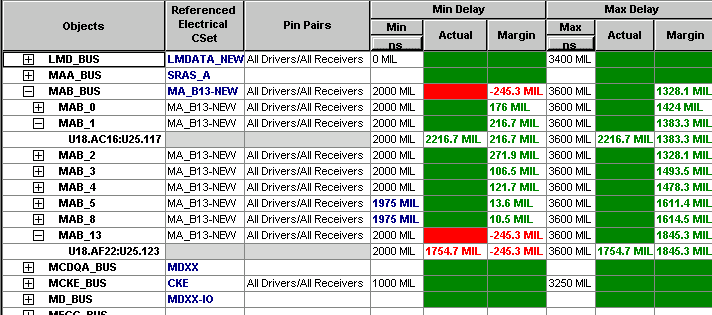
The following table and image take you through a typical scenario of analyzing propagation delay. Together, they explain how to interpret the analyzed results fed back to the worksheet.
Analyzing Propagation Delay

| Object | Cell Column | Comments |
|---|---|---|
|
LMD_BUS |
Referenced CSet |
CSets are set directly on the bus-level object. The cell is rendered blue. Members of the bus inherit the constraint values set on the bus. This is evident in the individual nets under the expanded MAB_BUS. Inherited constraint values are rendered black. |
|
LMD_BUS |
Min Delay Max Delay |
Cells are rendered green and do not contain values. This indicates that the last time the object (LMD_BUS) was analyzed, it was within the specified constraint values. For example, if the board was analyzed in an earlier design session, the analyzed values are not saved with the board database. However, the last analyzed state of the object (pass, in this case) is communicated back to the cell in the form of a solid color. To populate the cells with integral values, you must re-run analysis (choose Analyze – Analyze). You can also import saved analysis results (choose File – Import – Analysis results). |
|
MAB_5 |
Min Delay (Min) |
Nets 5 and 8 of MAB_BUS have overrides. The cell is rendered blue because the overrides were specified explicitly in each cell. Notice that the other members of MAB_BUS inherit their values from the constraint specified at the bus level. Therefore, these cells are rendered black. |
|
MCKE_BUS |
Min Delay/ |
Analysis failed, rendering the cells yellow. This was caused by an unplaced component attached to a net member of this bus. |
|
MAB_4 |
Min Delay Max Delay |
Analysis passes, rendering the cells green. Notice that only the Margin column contains an integral value; the Actual is solid. This is because the net has several hidden pin pairs. The cell is rendered a solid color to represent a pass/fail condition, because the cell can contain only one value. |
|
MAB_1 |
Min Delay Max Delay |
Analysis passes, rendering the cells green. Notice that both the Margin and the Actual columns contain integral values. This is because the net has been completely expanded (bus, to net, to pin pair). |
|
MAB_BUS |
Min Delay |
Analysis is in violation, rendering the cells red. Notice that both the Margin and the Actual columns contain integral values at the pin pair level of the MAB_13 net. This is because the net has been completely expanded (bus, to net, to pin pair). Also, notice that the net object that owns the pin pair displays a solid red in the actual column and an integral value in the margin column. This is because the worst-case violation is rolled up to the object that owns it. In this example, there is only one pin pair so it was rolled up. Again, if there were more than one pin pair in violation, because the Actual cell can contain only one value, the cell is rendered a solid color to represent a pass/fail condition. Worst-case constraint violations on child objects are rolled up the object hierarchy to the parent object. That is, pin pairs roll up to the parent net or Xnet, nets or Xnets roll up to the parent bus, and buses roll up to the parent design. In this way, you can work at any level in the object hierarchy and still be informed of a constraint violation on a lower-level object that is hidden. Finally, the same worst-case pin pair violation on the MAB_13 net is rolled up to the parent bus, MAB_BUS. |
View the next document: 06 - Constraint Difference Report
If you have any questions or comments about the OrCAD X platform, click on the link below.
Contact Us