00 - Introduction to Constraint Manager
Overview
Constraint Manager is a cross-platform, workbook- and worksheet-based application used to manage constraints across all tools in the Cadence PCB and IC Package design flow.
With Constraint Manager you can define, view, and validate constraints at each step in the design flow, from design capture (in OrCAD X Capture, Allegro System Capture and Design Entry HDL) to floor planning and design realization in OrCAD X & Allegro X PCB Editor & Presto. You can also use Constraint Manager with SigXplorer (covered in this guide) and Topology Explorer to explore circuit topologies and derive electrical constraint sets which can include custom constraints, custom measurements, and custom stimulus.
Disclaimer – This guide references all Constraint Manager functionality and does not separate or specify based on licensed product options. Available Constraint Manager functionality depends on the Cadence product platform and license tier that has been purchased.
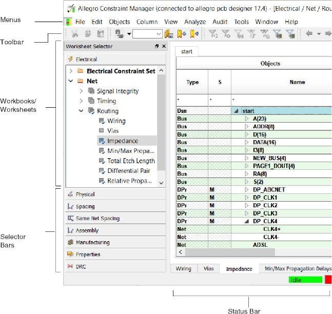
The following image shows Constraint Manager worksheets as launched from layout editors such as OrCAD X/Allegro X PCB Editor or APD. The worksheet hierarchy is different for Constraint Manager when launched in exploration mode, from Allegro System Capture, OrCAD X Capture, or Design Entry HDL.
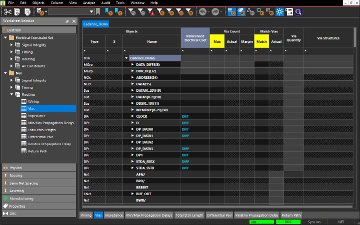
In Constraint Manager, you work with objects and constraint sets, which capture your design requirements.
The tool organizes constraints and Constraint Sets into the Physical, Spacing, Same Net Spacing, and Electrical domains. You then assign the appropriate constraint set to objects in your design, changing references (or re-defining the currently assigned constraint set) as your design requirements change. A constraint set can be referenced by any number of objects in your design.
Constraint Object Hierarchy
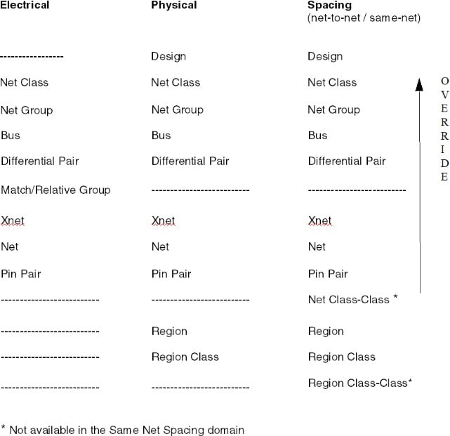
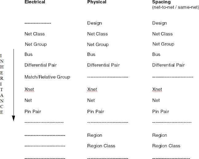
Constraint Manager enforces a precedence on objects in a design. Constraints that you specify at the top of the object hierarchy are inherited by the next lower-level object in the hierarchy.
Constraints that you define at the lower-levels of the object hierarchy take precedence over (override) the same constraints defined at the next higher-level in the object hierarchy.
This ordering of objects lets you define constraints at the highest level possible, only setting overrides on lower-level objects where necessary.
Work at the highest level possible in the constraint object hierarchy. For example, group individual address signals into a Bus. In this way, you only have to constrain the single Bus object once rather than having to repeat this process for each signal. Through inheritance, each signal in the Bus receives the constraint value assigned at the Bus level.
Constraint Object Override Hierarchy
Constraint Object Inheritance Hierarchy
Methods of Constraining Nets
- Inheritance
- Overrides
- Container Objects
- Referencing a CSet
Inheritance
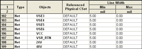
Inheritance enables the reuse of constraints by all components in the constraint-object hierarchy and helps them flow in a structured manner.
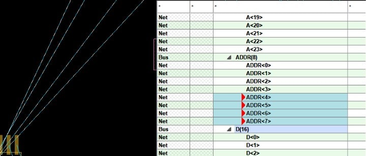
Each Net depicted in the following image inherits the 5-mil Min Line Width from the DEFAULT
Physical CSet.
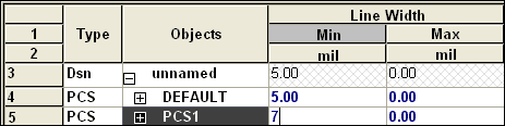
Overrides
You can directly set constraint values to override the inherited values.
To increase the line width of the voltage rails (Rows 106 - 109). As these are contiguous cells, simply dragging through them and specifying 7 mils is the most-direct method of constraining these nets
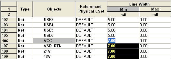
The overridden values, or overrides, appear in a blue tint. The advantage of constraining a container object is that it is quick and direct and it follows a constraint precedence; the disadvantage is that members of the container are fixed (though membership can be redefined) so constraints are not transferable to other container objects.
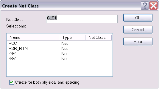
Container Objects
A container object is any group-object which is made up by grouping other design objects. For example, a differential pair, net class, net-class-class are container objects.
If you create a container object, such as a Net Class, you can constrain the container directly instead of constraining member nets individually. If you change the constraint value on the container, members of the container automatically inherit the change in constraint value.
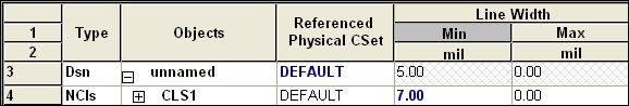
Constraint Manager presents Net Classes before Nets. The Nets from Rows 106 - 109 now appear, in collapsed form, in the Net Class container on Row 4.
If you expand the Net Class, you can see that the members inherit the new line width value of 7 mils.
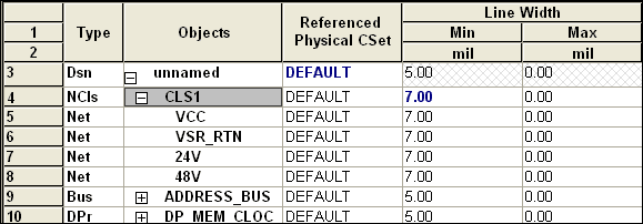
Use a net container object to group and constrain a small, focused collection of similar nets
Referencing a CSet
In the following example, create a Physical CSet and define a 7-mil Minimum Line Width constraint.
Next, associate the Physical CSet with the Net Class, whose members are the voltage rails that you want to constrain.
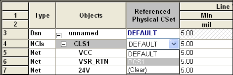
The advantage of referencing a CSet to impart constraints on a Net Class is that you can reuse the CSet to constrain similar Net Classes, with different members.
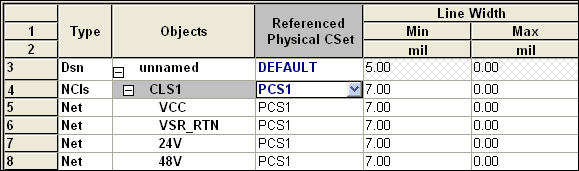
Use a reusable CSet, referenced to one or more container objects, to apply a broad brush approach to constraining nets.
Constraint Object Rules
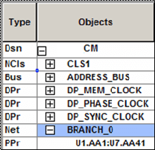
The Type column indicates the object type for the selected row, as depicted in the following table:
 |
Object Type |
|
|
Dsn |
Design |
|
|
DsnI |
Design Instance |
|
|
Lyr |
Layer |
|
|
PrtD |
Part Definition |
|
|
PrtI |
Part Instance |
|
|
GtI |
Gate Instance |
|
|
Bus |
Bus |
|
|
MGrp |
Match Group |
|
|
DPr |
Differential Pair |
|
|
Xnet |
Extended Net |
|
|
Net |
Net |
|
|
PPr |
Pin Pair |
|
|
NGrp |
Net Group |
|
|
NCls |
Net Class |
|
|
NCC |
Net Class-Class |
|
|
Rgn |
Region |
|
|
RCls |
Region Class |
|
|
RCC |
Region Class-Class |
|
|
Rslt |
Result |
|
|
PCS |
Physical Constraint Set |
|
|
SCS |
Spacing Constraint Set |
|
|
SNSC |
Same Net Spacing Constraint Set |
|
|
ECS |
Electrical Constraint Set |
|
|
RBnd |
Ratsnest Bundle |
|
|
RPPr |
Ratsnest Bundle pin pair member |
To bookmark any design element, select it in the Objects column, right-click and choose Bookmark – Object Bookmark. A square appears to the left of the object to aid you in locating the object. The bookmark follows the object across worksheets. You can also cycle through defined bookmarks, and remove them as well.
Do not use colon character in the object names. It is a reserved character used by Constraint Manager.
If Net Class-Class does not have an explicit CSet reference or directly-set values, it does not inherit constraints from the parent Class.
Differential Pair Rules
The following rules apply to differential pairs:
|
Model-Defined Differential Pair |
User-Defined Differential Pair |
|
|
|
|
|
|
|
|
|
|
|
|
|
|
Match Group Rules
The following rules apply to Match Groups:
- Specify a Match Group only in the Relative Propagation Delay worksheet of the Routing
workbook. - Set Match Group constraints for the entire group and override individual members of the group as desired, offering differing levels of delta and tolerance.
- Specify Match Group delays at the design-or the system-level. You can include a Match Group member in multiple Match Groups.
- If you are specifying a Bus- or Class-scope, create the Match Group in a CSet in the Electrical CSet folder.
Bus Rules
The following rules apply to creating a bus:
- You can create a bus in all net worksheets
- When used in conjunction with Allegro Design Entry HDL, Constraint Manager cannot create a bus. A bus is only realized with the appropriate property in the schematic
- A bus must be defined at the design-level instead of the system level.
Net Group Rules
- A net object can only be a member of one net group.
- Net groups are design specific.
Pin Pair Rules
The following rules apply to creating pin pairs:
- Physical, Spacing, and Electrical domains:
- Pins must exist in the object from which the pin pair is created.
- Electrical domain:
- Pin Pairs can only be defined in the following worksheets:
|
Electrical Workbook |
Electrical Worksheet |
|
All Constraints |
|
|
Timing |
|
|
|
|
Routing |
|
|
|
|
- Objects in the All Constraints and Timing worksheets must have a driver and a receiver as pin pairs.
- Pin pair length is the length of the etch path between the two pins, if the pins are routed. If not routed, the total manhattan distance of the ratsnest lines connecting the pins is used.
- Constraint Manager determines the longest/shortest pin pair length based on drivers and receivers. If there are no drivers or receivers, all pins in an Xnet are considered.
- For a relative propagation delay constraint, only the longest pin pair is determined.
Region Rules
The following rules apply to creating a Region:
- Specify a Region in the Region workbook in either the Physical or Spacing domain.
- Delimit a Region with a geometric shape, or a group of shapes, that you draw on a subclass layer in PCB Editor.
- Constrain a Region with a Physical- or Spacing-CSet. (recommended)
- Constrain a Region directly with explicit constraint values.
Regions are not supported in Design Entry HDL.
If Region Class-Class does not have an explicit CSet reference or directly-set values, it does not inherit constraints from the parent Class.
Region Class Rules
The following rules apply to creating a Region Class:
- Constrain a Region Class with a CSet. (recommended)
- Override individual members of a Region Class.
- Constrain a Region Class directly.
- Create a Region Class only in the Physical or Spacing domains.
Region Class are not supported in Design Entry HDL.
Region Class-Class Rules
The following rules apply to creating a Region Class-Class:
- Constrain a Region Class-Class with a CSet. (recommended)
- Override individual members of a Region Class-Class.
- Constrain a Region Class-Class directly.
- Create a Region Class-Class only in the Spacing domain.
Region Class-Classes are not supported in the Same Net Spacing domain, or in Design Entry HDL.
Constraint Manager Features
Constraint Manager offers the following features and benefits:
|
Feature |
Benefit |
|---|---|
|
Object Grouping |
Organize objects into easily-managed units, such as a Net Class, Bus, Differential Pair, or Match Group to make it easier to apply constraints to member objects. |
|
Object Group Type |
Group to view all the objects of a particular type. For example, all the differential pairs can be grouped together under Diff Pairs object type. This grouping reduces the number of rows and provides a tidy view of a worksheet. 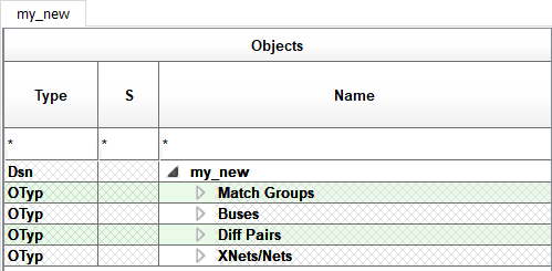
To work in legacy mode, set display setting for the Object Type Divider option in the View – View Options menu. |
|
Conceptual Definition |
Define constraints in a constraint set and later apply those constraints to net-related objects. |
|
Redefinable Constraints |
Rather than changing individual net-related constraints one-by-one, you can redefine a constraint set. All the objects that reference that constraint set get updated all at once. |
|
Cross-Probing |
|
|
Topology Exploration |
You can access SigXplorer from Constraint Manager to schedule pins and derive generic or net-specific constraints, which may include custom constraints, custom measurements, and custom stimulus. The resulting topology template data can be imported into Constraint Manager as an Electrical CSet. |
|
Design Reuse |
You can group constraints that satisfy a specific design requirement into an constraint set, which can be referenced within the active design or exported for reuse in a subsequent design. |
|
Cloning Constraints |
In addition to importing a constraint set or creating it from scratch, you can copy it, modify its parameters, and save it with a new name. |
|
Analysis |
Constraint Manager performs design rule checks, and simulations as necessary, to analyze the design. Analysis results are communicated by DRC markers, results populated in worksheet cells, simulation waveforms, and reports. |
|
System-level Constraints |
Constraint Manager can capture board-to-board interconnect constraints. |
|
Persistent Storage |
Constraint Manager maintains constraint information in either the board or the schematic database. |
|
Net, Component, and Pin Properties |
You can add and edit certain properties for nets, components, or pins in the Properties workbooks. |
|
Customizable |
You can create a custom workbook and worksheets that suit your work habits. |
|
Highlight and coloring functionality |
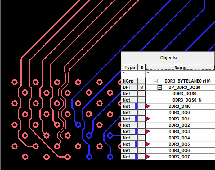
Constraint Manager displays a red triangle to the left of the object name, when the object is highlighted in the associated application.
Dehighlighting the object in the application removes the triangle in Constraint Manager. |
|
Constraint Manager displays a colored rectangle to the right of the object type when the object is uniquely colored in the associated application. In addition, a red triangle is displayed to the left of the object name.
|
|
|
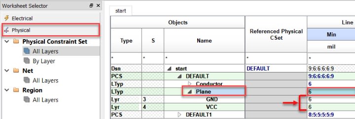
Hierarchical Layer Support |
The Physical and Spacing Constraint Sets support Hierarchical Layer Types Conductor and Plane. You can apply constraints only to hierarchical layer level and the values are inherited by the child layers of each group type.
To work in legacy mode, deselect the Layer Type option in Objects – Filter menu. |
How to Access Constraint Manager
Constraint Manager can be invoked using one of the following methods:
| From this tool | Choose this menu command |
|
Allegro X PCB Editor, Advanced Package Designer, or OrCAD X Capture |
Setup – Constraints – Electrical Physical Spacing Constraint Manager |
|
Allegro X System Capture |
Electrical Analysis – Constraint Manager |
|
Allegro Design Entry HDL |
Tools – Constraints – Edit |
You can also click the Constraint Manager icon in the toolbar.
Constraint Manager maintains constraint information in the board database when used with Allegro PCB Editor, in the package database when used with APD, or in the schematic database when used with Allegro X System Capture and Design Entry HDL.
The appearance of the Worksheet Selector, worksheets, and commands differ depending on whether Constraint Manager is launched in Exploration mode, from a front-end application, or a backend-application. For example, By Layer view of Physical and Spacing cells is not available in Constraint Manager, when launched from OrCAD X Capture or Allegro X PCB Editor.
The name of the tool from which you launch Constraint Manager appears in the Constraint Manager title bar. For example:
Constraint Manager (Connected to CAPTURE)
Constraint Manager in Allegro Physical Viewer
When invoked from the Allegro Physical Viewer Setup menu, read-only mode Constraint Manager launches with a limited functionality set. You can view the constraint information that a .brd file contains and all constraints appear in native delay values. You cannot modify or export these constraints due to minimal functionality available in Allegro Physical Viewer.
Read-only mode Constraint Manager includes all worksheets. However, SigWave or simulation actuals data are unavailable. Actual and Margin information is available for the constraints based on the current state of the design.
Although Allegro Physical Viewer does not let you change DRC modes, as they are inherited from the board, you can run DRC from PCB Editor to display actual data in Constraint Manager, which changes the database; then save it in Allegro Physical Viewer.
Constraint Manager Limitations when launched from OrCAD X PCB Editor
This topic covers all functionality available in Constraint Manager when invoked from Allegro X layout editors. When invoked from Allegro Sigrity licenses, or OrCAD X PCB Designer Professional or Standard, Constraint Manager launches with the following limitations:
|
Scripting is limited to only the supported commands. |
|
Match Groups can only be defined in net-level worksheets; they cannot be defined at the constraint set-level. |
|
Pin pairs can only be defined in net-level worksheets; they cannot be defined at the constraint set-level |
|
Signal integrity analysis is not supported. |
|
Timing analysis is not supported. The Timing workbook is not available. |
|
Custom measurements and custom stimulus are not supported. The Custom Measurements tab and the Custom Measurements workbook are not visible. |
|
Crosstalk analysis is not supported. The max xtalk and max peak xtalk design rule checks are not available from the Analysis Modes dialog box. |
|
Topology import and export are not supported. |
|
Simulation-based analysis is not supported. Only design rule checks can be performed. |
|
You create an Xnet through a signal model using Allegro PCB Designer or higher. |
|
PCB Editor |
|
|
OrCAD PCB Editor |
|
Constraint Manager Workspace
The Constraint Manager workspace contains the following components:
- Menus for command access
- Toolbar for quick command access
- Selector Bar for switching among domains and DRC and Properties Workbooks
- Worksheet Selector for selecting the appropriate worksheet
- Type column for identifying the type of object in the Objects column
- Worksheets for capturing, editing, and validating constraints
- Status Bar for feedback on object selection and constraint processing
- DRC Status indicator for checking the state of design rule checking
The Status Bar provides key information about cell contents, the state of objects, error conditions, and processes in your design.
Domain Selector Bars
Constraint Manager organizes constraints, and constraint sets by domain: Electrical, Physical, Spacing, and Same Net Spacing. You access each domain by clicking the appropriate Selector Bar, which is located at the bottom of the Worksheet Selector.
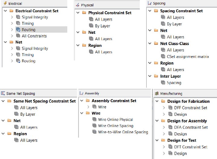
- In the Constraint Set Folders for all domains, you define generic rules and you create generic object groupings. You can later assign these rules to the appropriate net-related objects in your design.
- In the Net folders for all domains, you can create net-specific object groupings, and you can define certain net properties. In the Electrical domain, you can also create a constraint set based on the characteristics of a net object.
- In the Physical, Spacing and Same Net Spacing constraint folders, worksheets based on layer, or by all layers, contain Nets, Net Classes, and Regions.
Worksheet Selector
Use the Worksheet Selector to access the worksheet that you want to work in. Selector Bars let you access individual constraint worksheets, properties worksheets, and DRC worksheets, which you access by clicking on a Selector Bar. You can also undock and reposition the Worksheet Selector.
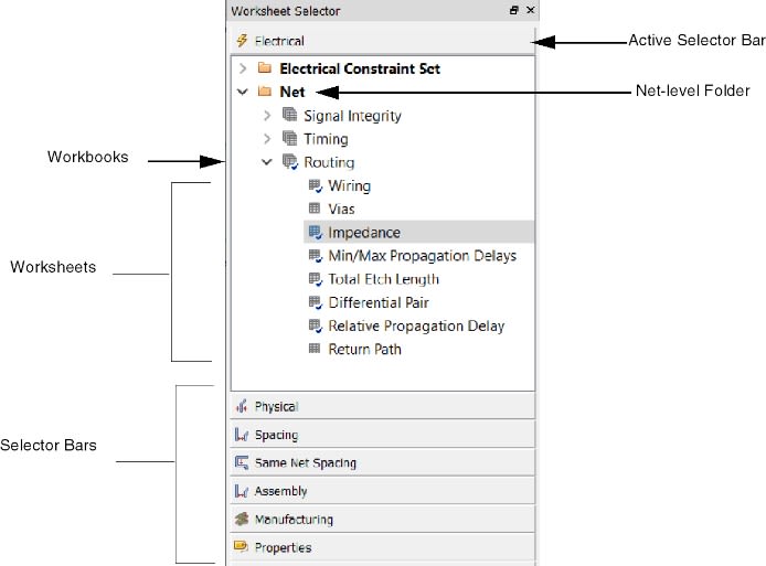
Grab the border of the Worksheet Selector and reposition it to get a full view of workbook and worksheet selector nodes.
Properties Selector Bar
Use the Properties selector bar to manage net, component, and pin properties.
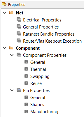
The Net folder provides you with a quick glance of electrical and general properties. Some cells in these worksheets cannot be edited.
The Component folder provides component coordinates, based on placement information, source data for third-party thermal analysis tools, and part definitions. Also included are electrical, thermal, and pin fabrication data. Some cells in these worksheets cannot be edited.
DRC Selector Bar
You can access the DRC browser from within the DRC worksheet, or from the Tools menu in the layout editor (Tools – DRC Browser).
Workbooks in Constraint Manager
Once you expand a parent Object Type folder, workbooks organize objects by design discipline. For example, the Electrical domain contains the Signal Integrity, Timing, Routing, and Custom Measurements workbooks. Also in the Electrical domain, the All Constraints workbook in the Electrical CSet folder consolidates constraints from all worksheets to give you a global view. Under to the All Constraints workbook is the User Defined folder, which contains constraints defined in SigXplorer.
The worksheet hierarchy appears different depending on how Constraint Manager is launched.
When you select a workbook, all worksheets that belong to that workbook appear in a shared worksheet window. You can use the Worksheet Selector to select a worksheet or select a worksheet by clicking the required tab in the workbook window.
When you launch Constraint Manager from a layout editor, the cells that are in view are populated first. As you scroll other cells into view, the layout tool updates hidden cells as they become visible in Constraint Manager.
The Analyze – Analysis Modes command controls DRC checks. Also, refer to the DRC State Bar, located at the bottom of Constraint Manager, adjacent to the Status Bar, to
- learn the state of DRC updates
- determine if DRCs are up-to-date for all enabled checks
Workbooks and Worksheets
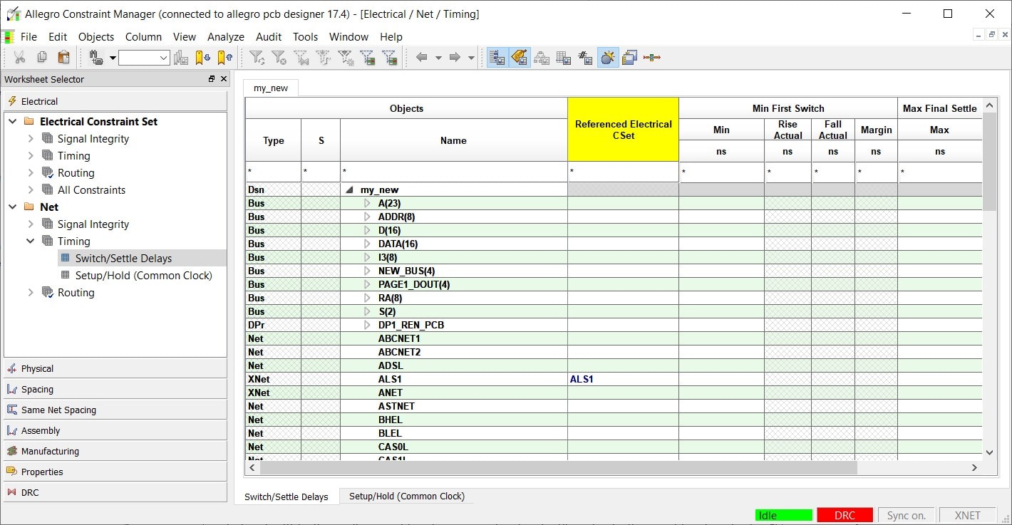
In the image above, notice how the Net object type folder is expanded to show Timing as the active workbook. The Timing workbook contains the Switch/Settle Delays and Setup/Hold worksheets. Notice how the worksheets in the Worksheet Selector correspond to the worksheet tabs in the active workbook. Also notice that the active workbook and the active worksheet within the active workbook are emphasized with color in the workbook selector.
If a workbook has only one worksheet, Constraint Manager updates the Worksheet Selector to contain only the worksheet (under the Object Type folder).
Physical and Spacing Workbook Views
Physical, Spacing, and Same Net Spacing CSet worksheets include layers, which correspond to the cross-section view of your design. Electrical worksheets do not include layers. You can view these layers collectively (All Layers) or individually (By Layer). You can also view them at the CSet-level or at the Net-level.
In the CSet object folder, you define CSets that are later applied to net objects. The All Layers view shows CSets in collapsed form and layers associated with a CSet in expanded form. The By Layer view (in the CSet folder) shows layers in collapsed form and CSets associated with each layer in expanded form.
All Layers / By Layer CSet Views
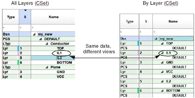
In the Net object folder, you define CSets based on existing CSets or existing constraints on Net objects. The All Layers view shows Container Net objects in collapsed form and Net objects in expanded form.
The Net, Net Class-Class (in the Spacing domain) and Region object types have a Referenced CSet column but do not have a By Layer view.
Same Net Spacing DRC Modes
As with other domains, you enable design rule checks for all layers through the Analysis Modes dialog box. However, in the Same Net Spacing domain, you can control design rule checks by layer.
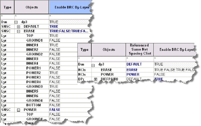
You define a Same Net Spacing CSet in the CSet folder, and later assign that CSet to a constraint object. In this way, you can enable or disable the CSet, effectively providing you with a granular level of control of setting constraint modes by layer. You do this by choosing TRUE or FALSE in the Enable DRC By-Layer column in the Options worksheet (see Figure Layer-based DRC Modes).
A by-layer constraint check depends on the mode for that constraint as set in the Analysis Modes dialog box. That is, if the individual DRC is not enabled in the Same Net Spacing Modes tab, Constraint Manager ignores the state of the Enable DRC By-Layer column.
Layer-based DRC Modes
Cells in Constraint Manager
Cells hold data, results, or calculations. Different colors or shades of colors are used in cells depending on the state of the design and on the scope of the data in the cell.
 |
Indicates a value inherited from a higher-level object, such as a CSet. |
 |
Indicates a Pass state — A value indicating that the cell falls within the set constraint limit. |
 |
Indicates a Pass state — A value indicating that all child cells of the parent object fall within the set constraint limit. |
 |
Indicates that the value is set directly in the cell. Also called an override. |
 |
Indicates a value that cannot be computed. Hover the mouse over the yellow cell and observe the message displayed in the status line, located at the lower-left corner of Constraint Manager to see the reason.
You can set certain constraints, such as differential pairs, in more than one domain. Constraint Manager indicates a constraint edit in one domain by coloring the cell of the same constraint in the other domain yellow. |
 |
Indicates a Fail state — A value indicating that the cell violates the set constraint limit. Constraint Manager rolls up worst-case Margins to higher-level objects. |
 |
Indicates a Fail state –— A value indicating that a child cell of the parent object violates the set constraint limit. |
 |
Indicates a cell which is not applicable to the object. These cells never contain values. |
 |
Indicates a cell that cannot be edited. |
 |
The red bar to the right of the cell indicates that the cell contains a formula. |
 |
Indicates a bookmarked cell. |
To guide you in entering data into a cell, right-click in the cell and choose Change.
Constraint Manager User Interface Controls
Constraint Manager uses the standard Windows and worksheet controls.
The Constraint Manager user interface supports local language settings. For more information on how to switch the language of the user interface, refer to Setting Up Local Language Preferences in Allegro X User Guide: Getting Started with Physical Design.
Constraint Manager honors the local language settings of the tool from which it is launched.
| Task | Feature | Usage |
|---|---|---|
|
Accessing commands |
|
Choose the menu commands from the menu bar located at the top of Constraint Manager to access commands. |
|
Click an icon to run a command. |
|
|
Press any of the following keys along with the Ctrl key: You can access many other commands by pressing the Alt key along with the underlined character in the menu command. You can also assign custom shortcuts. |
|
|
Depending on the object selected, you can right-click to quickly access a command to act on that object. |
|
|
Resizing and Placing Worksheets |
|
You can drag the Constraint Manager window and individual worksheets, to reposition them on your desktop. |
|
Resize the Constraint Manager window or an individual worksheet open within Constraint Manager by dragging the border. |
|
|
Minimize an open worksheet to an icon or maximize it to focus only on that worksheet. |
|
|
Click the Close [X] button at the top right-corner of the worksheet to close a worksheet. Constraint data is not lost when you close a worksheet. |
|
|
Viewing a Worksheet |
|
Click and drag an open worksheet to reposition it. |
|
Expand [+] or collapse [-] the object tree-structure in Worksheet Selector to work at any object level in the hierarchy from the system level to the pin pair level. |
|
|
View all the open worksheets arranged one-behind-the-other from the Window – Cascade menu command. |
|
|
View all the open worksheets simultaneously from the Window – Tile menu command. Each open worksheet is automatically sized to accommodate the size of the Constraint Manager window. |
|
|
Duplicate the content of the active worksheet in a new window to focus your view on different objects in the same worksheet. |
|
|
When you expand a constraint discipline (Signal Integrity, Timing, Routing) from the worksheet selector, all the worksheets within the discipline open in separate tabs. You then click a related tab to activate the desired worksheet. |
|
|
When you modify rows of the worksheet in focus (for example, scrolling down or expanding a bus), Constraint Manager promotes the same modification to all worksheets that have synchronization enabled. |
Accelerator Keys in Constraint Manager
Constraint Manager provides function keys and modified function keys for quick access to common functions.
| Function | Keys |
|---|---|
|
View options |
|
|
Rename |
|
|
|
|
|
Analysis modes |
|
|
Analysis settings |
|
|
Analyze |
|
|
Find |
|
|
Find next |
|
|
Find previous |
|
|
Open a new window on the active worksheet |
|
|
Move to the next open worksheet |
|
|
Move to the previous open worksheet |
|
|
Open next worksheet tab |
|
|
Open previous worksheet tab |
|
|
Close the active worksheet |
|
|
Select a contiguous range of cells |
|
|
Select a non-contiguous range of cells |
|
|
Expand object rows |
or
|
|
Collapse object rows |
or
|
|
Cut |
|
|
Copy |
|
|
Paste |
|
|
Delete an object or cell content |
|
|
Enable object bookmarks |
|
|
Navigate to next object bookmark |
|
|
Navigate to previous object bookmark |
|
View the next document: 01 - Constraint Sets
If you have any questions or comments about the OrCAD X platform, click on the link below.
Contact Us