07 - Constraint Compiler
Overview
Constraint Compiler is a mechanism for translating design constraints from an external source directly into Constraint Manager. Constraint Compiler introduces constraints per manufacturer guidelines at the interface level in a design. The compiler can insert initial constraint or update the existing constraint information in a design. To create specific rules for various interfaces in a design, Constraint Compiler uses connectivity information (buses, differential pairs, nets, and so on) of a design in conjunction with data agnostic constraint information provided by the manufacturer.
Constraint Compiler is available with the following product licenses:
- Allegro X PCB Designer with High-Speed Option
- Allegro X Venture PCB Designer Suite
- Allegro X Enterprise PCB Designer Suite
- Allegro X Advanced Package Designer (Packaging)
- Allegro X Design Authoring (Schematic)
Various manufactures provide EDA design guides to ensure that the customers leverage the technology to its fullest extent and be able to develop products that perform as expected. These design guides are specified at the interface level. The PCB designer interprets these guidelines and apply appropriate rules in the layout tool. Incorrect understanding of these rules leads to under or over constraining of the design. To determine the appropriate requirements for constraints, consulting reference designs and taking design review services helps, but it increases the design schedule that can impact the overall product schedule. Constraint Compiler aids designers by translating the manufacturer’s design guides automatically into Constraint Manager.
Working with the Constraint Compiler
The power of Constraint Compiler is the ability to leverage data-agnostic constraints that can be developed once and validated and placed in a central library for future use in other designs. All the designs are not identical and may have slightly different net names or component reference designators. Constraint Compiler acknowledge this fact and provides a mapping table to correlate constraint and design-specific information and generates a standard Constraint Manager difference report to review changes that will be made to the design. You can run the compiler in either the validation mode (report-only mode) or the apply mode to incorporate the changes to the design with compiler options to merge or replace existing constraints.
The following illustration shows an overview of the process flow of Constraint Compiler.
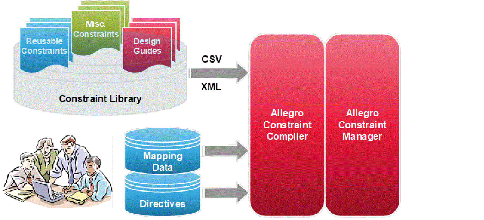
After the design guides are transposed into the agnostic format, they can be stored in the constraint library for use in future designs. The data tables in the constraint library need to be structured to be generic as possible so it can be used in any design. Any design-specific objects need to be stored as alias variables that can be updated through a mapping data table on a per design basis. Special table keys can be entered in the constraint library data table for filtering tables using the query functions of the compiler.
Advantages of Constraining Designs Using Constraint Compiler
The Constraint Compiler is capable of redirecting constraint information with no manual intervention and without introducing any errors into a design. Some of the advantages of using Constraint Compiler are as follows:
- Provides quick entry of constraints without any knowledge of Constraint Manager.
- Provides a way for manufacturers (silicon vendors) to develop specification tables to supplement their design guides.
- Constraint management can be done at the abstract level instead of the design level.
- Constraint information is easily transferred using a single source into multiple designs. This process ensures consistent constraint data in multiple designs and does not require export or import of technology files (.dcfx,.tcfx).
- Facilitates automatic generation of constraint objects (Differential pairs, Net Classes, Net Groups, Match Groups, and expanded Constraint Sets) .
- Constraints specified at the top of the object hierarchy are propagated down to the lower-level objects without any effort.
- Controls the versions of golden library constraints.
Applying Constraints using Constraint Compiler
To apply constraints in a design using compiler, do the following:
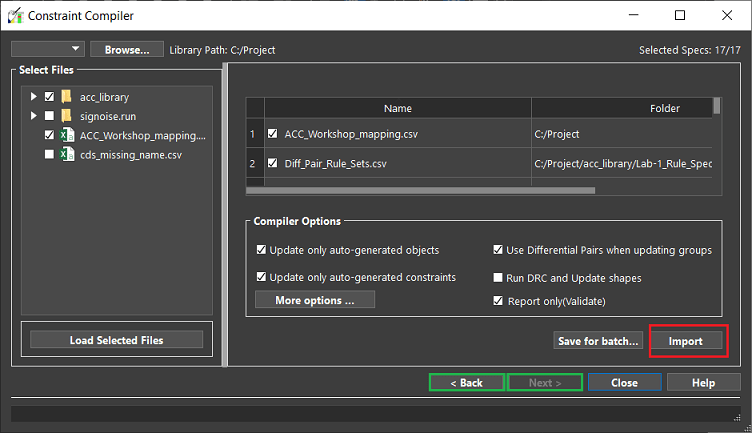
- Open Constraint Manager and choose Tools – Constraint Compiler.
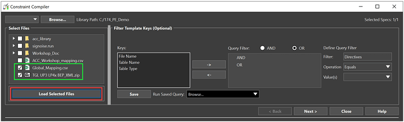
The Constraint Compiler dialog box appears. - To select relevant library files, select one of the following two ways:
- In the Select Files browser, expand library folders and select .csv/.xml/.zip files based on their names and dependencies.
- Click the Load Selected Files button.
Or - In the Select Files browser, enable the top-level library folder to select all the files.
- Click the Load Selected Files button.
- In the Keys section, double-click a key name to select it for query filter.
- In the Query Filter pane, select the key and change its value in the Define Query Filter pane.
- Optionally, click the Save button to save the query settings.
- Click the Next button to view the query results.
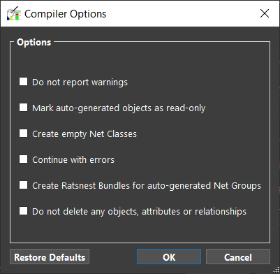
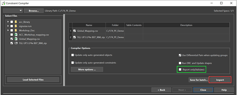
- Configure the options in the dialog box.
- For more compiler setting, click More options.
- To validate the compiler results, enable report only (Validate) compiler setting and click Import.
Compiler generates Allegro Constraint Compiler Report to review any errors and warnings before applying constraints. - Verify the report for new constraints and close the report.
- Click Import.
- Click Close.
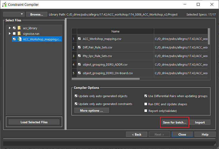
Running Constraint Compiler in Batch Mode
Constraint compiler can be run in batch mode using a SKILL API cmxlCompile(). This SKILL function requires an ACC configuration file (.accx) which is generated from the Constraint Compiler interface.
Follow the steps to run the compiler in the batch mode:
- Choose Tools – Constraint Compiler.
- To import tables, select them from the Select Files section.
- Click Load Selected Files followed by the Next button.
- If needed, set Compiler options and use More Options to adjust the other compiler settings.
- Click Save for batch and save the file as acc_batch.accx.
- To load the ACC configuration file, create the following SKILL script acc_batch_load.il:
procedure(acc_batch_load()
axlCMDBInit()
design = cmxlFindObject(REDS_DESIGN_OBJ)
when(design
cmxlDBSkillInit(design)
cmxlCompile(design, "./acc_batch.accx")
)
axlCMDBExit()
)
- To run the SKILL script in layout editor, enter the following commands in the command window:
skill load("acc_batch_load.il")skill acc_batch_load
Troubleshooting Constraint Compiler Errors
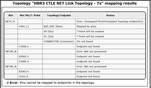
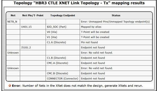
The Compiler reports error during import in some cases. To identify and fix the issues, do the following:
- Inconsistent topology: Applying a Net topology to an Xnet, or an Xnet topology to a single Net in the design.
- Review mapping results in report, identify the problem, and take corrective action.
- Generate Xnets in the design to resolve the issue.
- Constraint table alias to design name association is not included in the name mapping table.
- Compiler automatically generates a log file with separate name tables by Interface identifying the required alias to design specific name as follows:
- Name mapping specification for the Interface exists but some aliases are missing. Following is a Name and Object Rule table scenario:
cds_missing_alias.csv: Copy the Type and Alias cells to Name Mapping table for the design and enter the design specific name.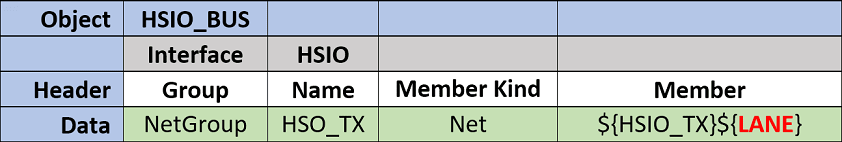
- Name mapping specification for the Interface does not exist. Object Rule table scenario which contains aliases but no mapping:
cds_missing_name.csv: Copy the entire name table to name mapping table for the design and specify the design specific name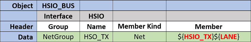
- Copy log files information into the Mapping Name table for the design prior to running the compiler.
- Name mapping specification for the Interface does not exist. Object Rule table scenario which contains aliases but no mapping:
- Name mapping specification for the Interface exists but some aliases are missing. Following is a Name and Object Rule table scenario:
Constraint Compiler Options
The Complier does not delete any existing constraint information. It only adds new constraints or modify the existing constraint values as specified in the data tables. You can change the default behavior in the Complier Options section and import the constraints into the design.
To modify the selection of files, you can navigate using Back and Next buttons and verify the compiler report generated each time you run validation. To apply constraints, click Import.
As an alternative to the .csv files, you can select XML Constraint Data Set ZIP, or if already extracted, select the Design.XML file and Global Mapping Table to apply the constraints in a design.
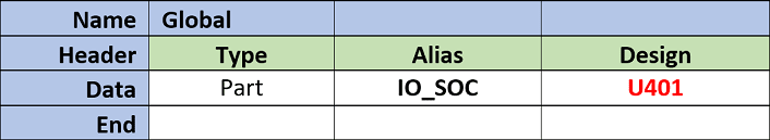
The following mapping table example shows a single table with the name Global and is used across all Interfaces included with the Constraint Data Set.
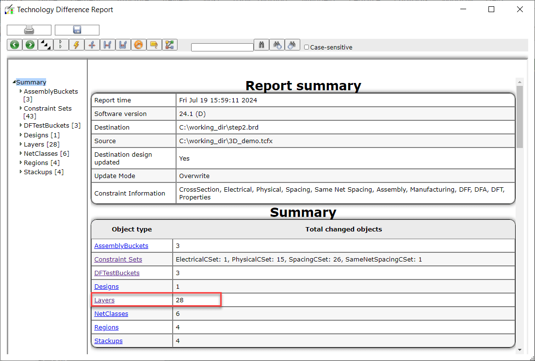
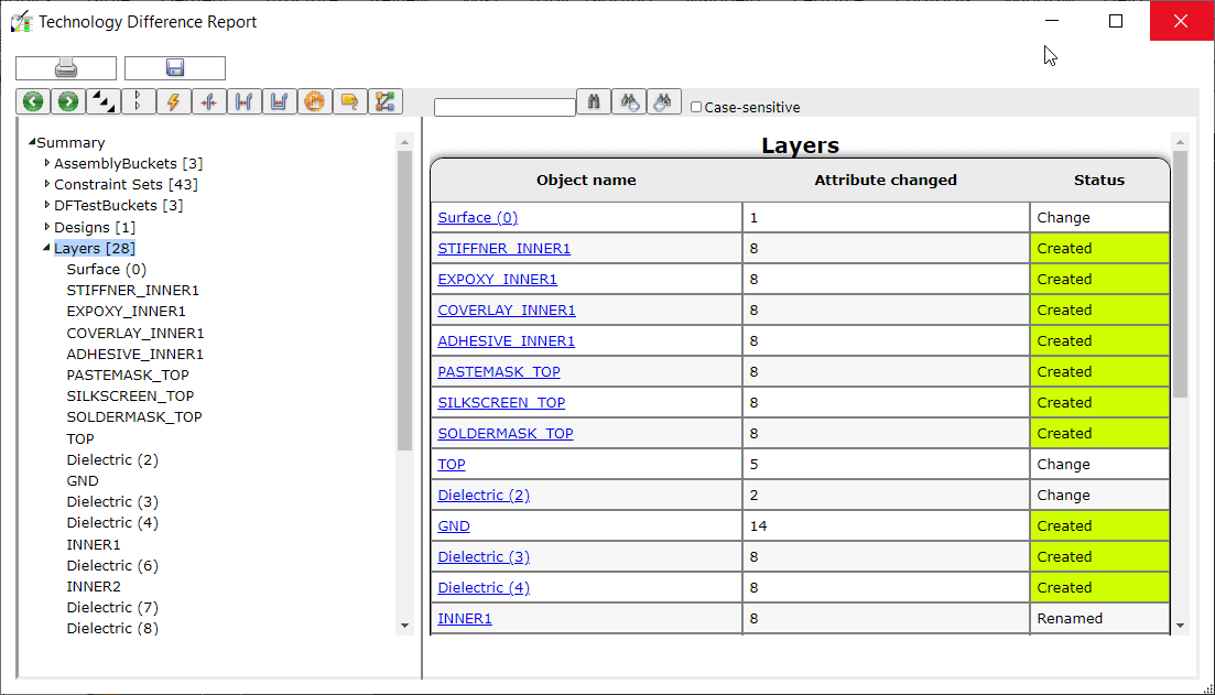
The compiler processes all the files and displays the summary in the constraint difference report. The report contains all the warnings, errors, and the changes made to the design. Expanding summary items displays the respective updates in the right pane of the report viewer.
In Constraint Manager, constraints objects created by the compiler are labeled with an "A" in the sub-filter field and indicating an Auto-generated object. These objects are read-only and can be updated only by the compiler.
Data Tables in Constraint Manager
For the complier to read and apply the constraints information in a design, two types of tables are needed: object tables and mapping tables. The object tables contain agnostic constraint information and the mapping tables associate the agnostic constraints to the design-specific objects. The tables are in the .csv and .xml schema format and have the same structure.
Constraint Manager – Data Table Structure
All the tables follow a general format with the differences of additional columns. The following image shows a sample data table:
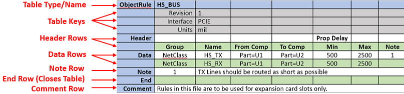
| Row Name | Row Description |
|
Table Type and Name |
Identify the table usage. It begins with a table and concludes with an End statement in the first column. A file can contain multiple tables and/or table types. |
|
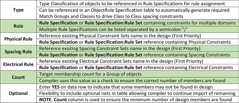
Table Keys |
Provide specific information that can be queried by the compiler to narrow down the table selection.Table keys are specified between the Table Type/Name and the Header rows. The reserved keys are as follows:
|
|
Header Rows |
Specify the data type or constraint type information. Header rows are specified between Table Keys and Data Rows. The name of a column header with semicolon separators can span two rows. For example, Prop Delay: Min shown as Prop Delay in the first row and Min in the second row. |
|
Data Rows |
Specify constraint values and requirements. Data rows are specified between the Header Rows and the End statement. |
|
Comment Rows (;) |
Communicates design intent. |
|
Note rows (#) |
Adds notification to compiler report. |
Types of Data Tables in Constraint Manager
The Object and Specification tables contain agnostic constraint information for common design circuitry and the Mapping table associates the agnostic constraints to design specific objects. The compiler reads and combines all this constraint data to fully define the constraint requirements for a design.
- Constraint Manager – Mapping Name Table
- Constraint Manager – Global Mapping Table
- Constraint Manager – Topology Table
- Constraint Manager – Object Table
- Constraint Manager – Rule Specification Table
- Constraint Manager – Object Rule Table
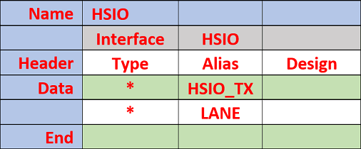
Constraint Manager – Mapping Name Table
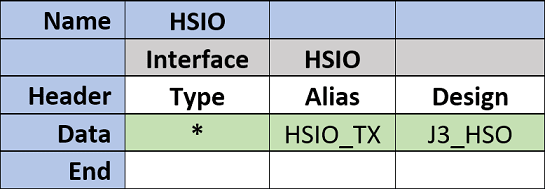
Mapping table associates the design specific name to a string alias that is defined in other tables. For example, Part (Component), Net or "*" (all object types). The compiler reads this table to map alias place holders referenced in the data tables to be replaced with design specific names. The mapping name table provides a central location to remap all the aliases to the design specific names.
Column Header Description
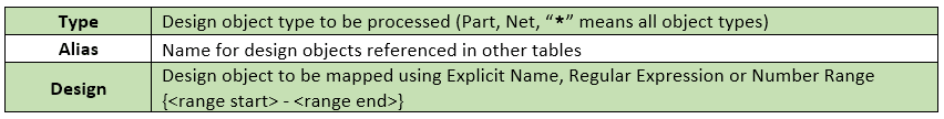
Design Object Selection
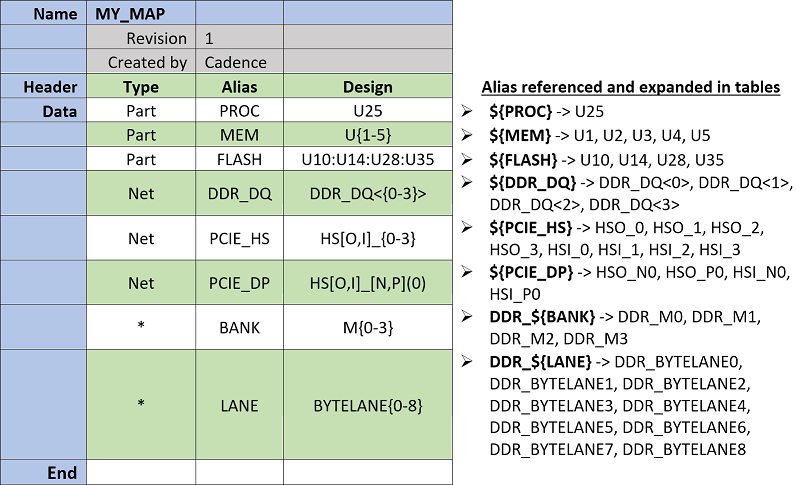
Selection of design object names can be done using explicit name, partial name with number range or regular expression or a combination of both. For example,
- Number range for nets DDR_DQ<7> through DDR_DQ<16> is DDR_DQ<{7-16]>
- Regular expression for nets DDR_CK0_N and DDR_CK0_P is DDR_CK0_[N,P]
- Regular expression and number range for nets HSI_N0, HSI_P0, HSI_N1, HSI_P1 is HSI_[N,P]{0-1}
Sample Mapping Table
The following image shows a sample mapping table entries for a table MY_MAP.
Compiler Results
If the compiler detects an alias place holder without appropriate mapping to a design object, it reports an error and automatically generates a log file. The log file contains separate Name tables by Interface identifying the required alias to design specific name.
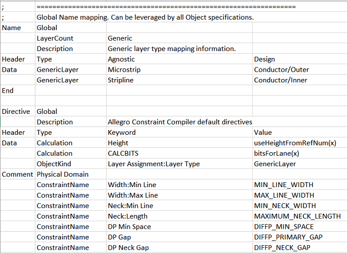
Constraint Manager – Global Mapping Table
The Global Mapping table is used to provide common mapping across all data tables. You can create this table with name ACC_Directives.csv and save in the compiler directory inside your current working directory.
The default global mapping table exist in the installation directory at <installation_directory>\share\pcb\consmgr\CDS_ACC_Directives.csv.
Sample Global Mapping Table
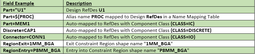
Constraint Manager – Topology Table
The Topology table is used to define routing sections for a Net or an Xnet which can be pin to pin or different transition points along the routed interconnect. These routing sections can then be referenced in an Object Rule table to drive the Physical, Spacing, and Electrical constraints for the specific section.
Column Header Description
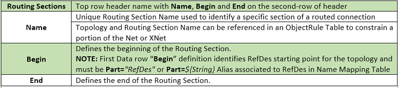
Begin and End Supported Fields
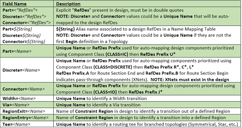
Mapping Examples (Begin/End)
What is a Topology and how can it be used?
Physical and spacing constraints are defined across the entire Net or Xnet, whereas electrical constraints can be defined at the lower pin pair level. In complex designs, constraints need to be defined on specific sections of the routed connections beyond basic pin pair or region-based rules, such as fanout, pin field, breakout, main route, and so on. To facilitate this, the begin and end points of routing sections can be defined based on a physical representation in the design (via, width, and region entry/exit transitions).
The following illustration shows net sectioning to drive different constraints per routing section.
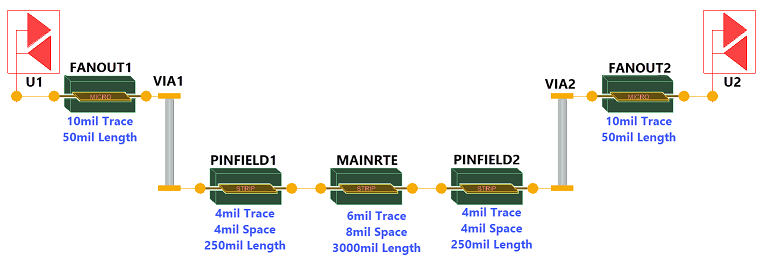
Topology graphical representation is not available in the layout editor.
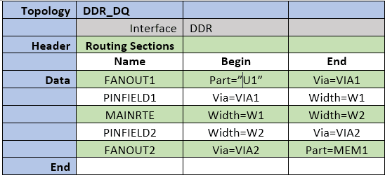
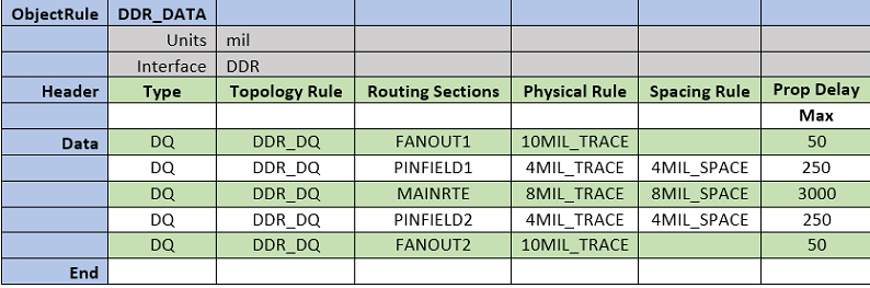
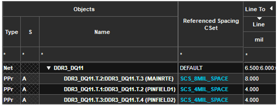
For this topology the topology table and object rule table are as follows:
Topology table drives constraints on a section of a net. After constraints are loaded, special transition Rat-Ts becomes visible on the canvas and dynamically snap to the appropriate location as defined in the topology. The following image show the canvas view of Rat-Ts that are displayed as diamond shape with cross.
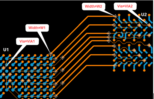
These transition Rat-Ts define begin/end points of the route representing the routing section with constraints being checked accordingly. This approach provides more flexibility beyond traditional region-based constraints as well as electrical constraints specific to a pin pair.
The show element command on these Rat-Ts displays information of constraints, routing sections and transition type as shown in the following image:
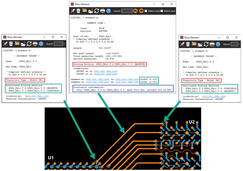
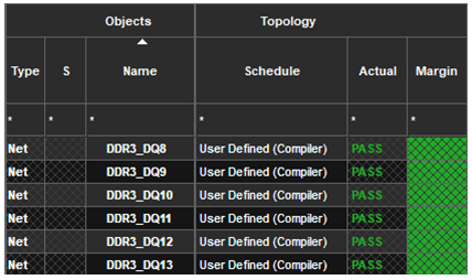
In Constraint Manager, you can view the topology schedule and electrical routing section constraints.
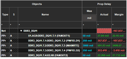
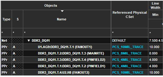
Similarly, spacing and physical routing section constraints can be verified in Constraint Manager.
Notes
- It is recommended to apply topology-based constraints on routed nets to verify that the routed interconnect has the required transitions to start checking constraints accurately.
- If a routed interconnect does not have the required transition to identify the routing sections, transition Rat-Ts remain floating until the routing is corrected. Use show element for transition Rat-Ts to resolve the issue. When updated, routing automatically snaps the Rat-T to its appropriate location.
- You can apply topology-based constraints on unrouted nets. Some of the interactive routing commands automatically identify a transition and start checking constraints accordingly.
- Topologies with Xnets indicate that the appropriate Xnets already exist in the design. This information can be checked from the compiler report and can be used to update a design.
- In some cases, a routed interconnect may or may not contain all the required transitions as outlined in the topology and a scheduled DRC error is generated. For example, a pin field trace neck down may not be required on connections on the edges of the BGA pin field. As a result the transition will be left floating.
- Topology using TEE= transitions does not snap to the appropriate branching Tee location and reports a schedule DRC. TEE= transition are displayed as a solid-fill diamond shapes. Show Element on DRC error helps to determine the transition location and the Rat-T can be moved manually to resolve the schedule error.
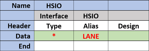
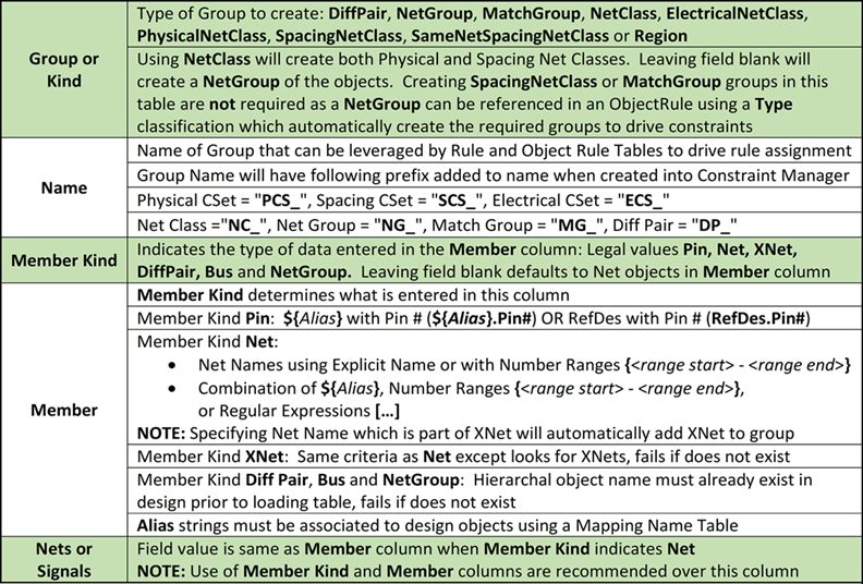
Constraint Manager – Object Table
The Object table creates various constraint objects, their members and type classifications for reference in other tables. Rule Set and existing Constraint Set references can be made during object group creation as well a Count check to ensure that all the expected members are selected in the design.
Column Header Description

Optional Column Header Description
Byte Lane Bit Calculator: $ByteLane(x, y, z)
- x = Byte Lane number, starting from 0
- y = Number of BITS in each Byte Lane
- z = Number of digits in each BIT number
Results: Generates a series of data bit numbers based on current Byte Lane being processed.
Examples
- Enter $ByteLane(0,8,1) expands to number pattern: 0,1,2,3,4,5,6,7
- Enter $ByteLane(1,8,2) expands to number pattern: 08,09,10,11,12,13,14,15
Byte Lane 2nd Diff Pair Calculator (x4 Mode Data Strobe): $x4HighDP(x, y, z)
- x = Byte Lane number, starting from 0
- y = Total Number of Byte Lanes
- z = Number of digits in each BIT number
Results: Generates 2nd Diff Pair number in a sequence based on Total number of Byte Lanes and current Byte Lane being processed.
Examples
- Enter $x4HighDP(0,8,1) in column expands to number pattern: 8
- Enter $x4HighDP(1,8,2) in column expands to number pattern: 09
Byte Lane Calculators requires NetGroup and Member entries in row to share a common Byte Lane number to determine which Byte Lane is being processed. Using an Alias in both the entries to cycle through each Byte Lane number provides the linkage.
Net Selection
The Nets or Signals column entries are limited to Xnet/Net objects, which can be selected in the design using explicit net names or with a partial net name and a number range specified within curly brackets {n-n}. For more complex net name selection, regular expressions are also supported and if the net name contains a square bracket, a forward slash "\" can be used to treat it as a regular character. If selecting all Xnet/net members for group assignment, which are already members of a different type of group (Net Class, Net Groups, Differential Pairs), then the existing group gets added to the newly created group. For example,
- Selecting all the members of a Net Group to create a Net Class, the Net Group object gets added to the Net Class
- Select both the members of a Differential Pair for addition to a Net Class, the Differential Pair object gets added to the Net Class
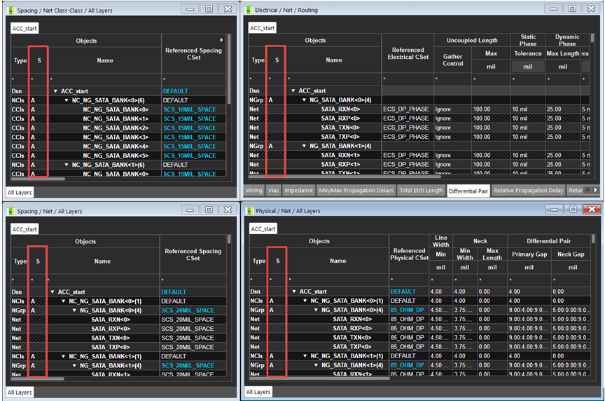
Objects created by the compiler are labeled with an "A" indicated as auto-generated objects in Constraint Manager.
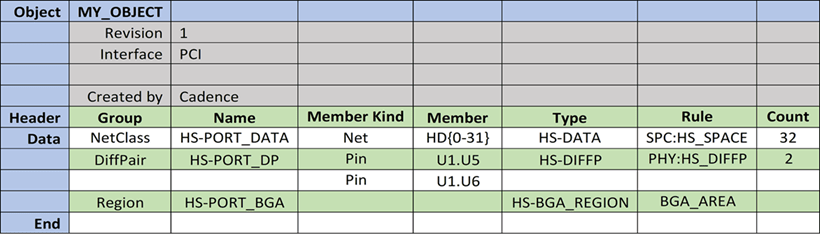
Sample Object Table
Compiler Results
- Net Name string ending with multiple numbers within a number range specified within curly brackets "{ }"
- Spacing Net Clas
s HS-PORT_DATAthat contains netsHD0, HD1, HD2, HD3, HD4, … HD31assigned to rule setHS_SPACE from theSPCrule specification. When imported into Constraint Manager,- Net Class name starts with prefix
NC_ - Spacing CSet name starts with prefix
SCS_
- Net Class name starts with prefix
- Differential pair
HS-PORT_DPmember net namesHSON(0)andHSOP(0)are extracted from the device pins U1.U5 and U1.U6 and then assigned to rule setHS_DIFFPfrom thePHYrule specification. When imported into Constraint Manager,- Differential pair name starts with the prefix
DP_ - Physical CSet name starts with the prefix
PCS_
- Differential pair name starts with the prefix
- Region
HS-PORT_BGAcreates physical and spacing region objects in Constraint Manager assigned toBGA_AREArule specification- Basic physical and spacing constraints can be assigned to a region in an Object Table to control constraints for all nets entering the region
- To create Region Class or Region Class to Class constraints, specify them in an Object Rule table using Type classification passed from the Object Table
Region object in Constraint Manager needs to be manually assigned to Constraint Region shape on the canvas.
- When imported into Constraint Manager, physical CSet name starts with the prefix
PCS_and spacing CSet name starts with prefixSCS_
Constraint Manager – Rule Specification Table
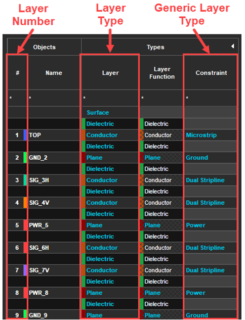
The Rule Specification table is used to capture Electrical, Physical and Spacing requirements to create an associated Constraint Set in Constraint Manager. Physical and Spacing rules can be defined using existing Layer type or Generic layer designations in the stackup or by layer in the stackup using the Layer number(s).
The DEFAULT Physical and Spacing Constraint Sets in Constraint Manager can be used as a starting point with only the constraints entered in the table updated.
The compiler determines which Constraint Set type (domain) to be created based on entered rules in the Rule Specification. For example, specifying a "Width: Min Line", "Line To Line", and "Max Length" in one Rule Specification generates Physical, Spacing, and Electrical CSets for the three different constraint types.
To support the rules which can be present in multiple domains, the Rule Specification type can be updated to include the target Domain (prefix to Rule):
- PhysicalRule,<table name> (Physical domain)
- SpacingRule,<table name> (Spacing domain)
- ElectricalRule,<table name> (Electrical domain)
For example, Differential Pair rules can be defined in the Electrical Domain (all layer’s rules) and Physical Domain (layer-specific rules)
A Rule Specification can be defined to create only one CSet for each domain or multiple CSets per domain by specifying different Rule Set names in the header using the Rule column (for example, Rule=<rule set name>).
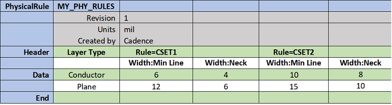
Derived Constraint Set Support
By default, the Physical and Spacing DEFAULT CSet from the design is used as a starting point with the values in the table updated to form a new Constraint Set. A special key can be used in a rule specification to specify which CSet is used as a starting point.
- Table keys are the rows above the header row and below the table name row.

Column Header Description
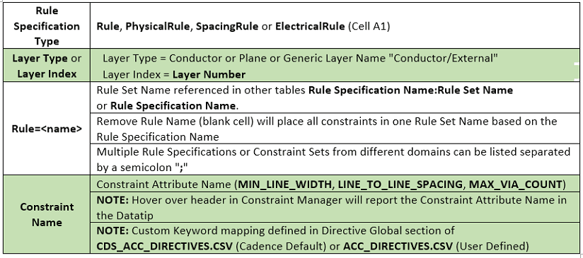
Sample Rule Specification
Compiler Results
- The default Physical CSet gets copied to PCS_CSET1 with the following values:
- For Conductor layers: Min Line Width=6 mil and Neck Width=4 mil
- For Plane layers: Min Line Width=12 mil and Neck Width=6 mil
- The default Physical CSet gets copied to PCS_CSET2 with the following values:
- For Conductor layers: Min Line Width=10 mil and Neck Width=8 mil
- For Plane layers: Min Line Width=15 mil and Neck Width=10 mil
- Rule Set name with prefix PCS_ added to the new Physical CSet name.
Multi-Row Header Rule= designation indicates the beginning of a Rule Set with all constraint columns included in it until another Rule= designation starts.
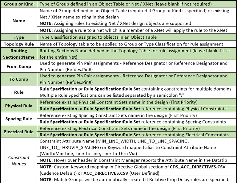
Constraint Manager – Object Rule Table
The Object Rule table is used to assign rules to objects in a design. Rules can be assigned by referencing group or Kind name and type classification defined in an Object Rule table or an existing Net or Xnet in the design. The primary use of the Object Rule table is to define explicit pin to pin rules of a group of objects by specifying a from-to component designation. After these pin-pairs are defined a rule set or an existing CSet can be applied to the appropriate object level (Net Class, Net Group, and so on).
You can specify one-to-many constraint expansion that propagate rules down to the lowest level while generating all supporting objects. For example, if relative propagation delay rules are defined, the compiler automatically creates the required match groups. In addition, part assignment can be driven by a mapping table to create many pin-pair relationships with associated match groups.
Relative Propagation Delay rules are only supported when an explicit pin-pair is specified in the table using from component to component. Specifying global or local Scope or longest pin-pair, longest driver/receiver, and all drivers/all receivers are ignored.
Column Header Description
Sample Object Rule table
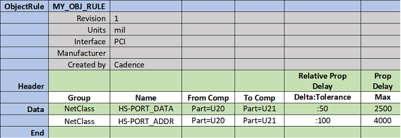
Compiler Results
- Generates Match Group HS-PORT_DATA with the pin-pairs between U20 and U21 for Net Class HS-PORT_DATA with the following rules:
- Relative Propagation Delay Tolerance = 50
- Max Propagation Delay = 2500
- Generates match group HS-PORT_ADDR with the pin-pairs between U20 and U21 for Net Class HS-PORT_ADDR with the following rules:
- Relative Propagation Delay Tolerance = 100
- Max Propagation Delay = 4000
- Relative propagation delay with an empty Delta field matches all the match group members within the Tolerance:
- Setting the Delta field to 0 to match all match group members to the longest pin to pin manhattan length within the defined Tolerance (+/- Tolerance).
- Setting the Delta to anything other than 0, on a specific net, gets treated as a +/- offset to the member which yields the longest pin to pin manhattan length within the Tolerance.
- Propagation delay keeps the pin-pair connection below the Max length.
- When imported into Constraint Manager, match group name have prefix MG_ and based on the Net Class name.
Object Rule table (Match Group Support)
In many cases, Match Group membership is based on a group of nets that already exist in other groups (Net Group, Net Class or Bus). Referencing these groups in an Object Rule table, with Relative Propagation Constraints, automatically generates the required Match Group without the need of generating multiple groups with the same membership.
Defining Match Group Membership in an Object Rule table
Match Groups as well as their membership can be created in an Object Rule table though it is not a recommended practice. The following are some of the effects of creating Match Groups in an Object Rule table:
- Match Groups are created only with Xnets as their members while the Relative Propagation Delay rules need to be defined in an Object Rule table.
- Net Group membership can be used in an Object Rule table to generate Match Groups when Relative Propagation Delay rules are assigned
- Match Groups can only be constrained using the appropriate Driver/Receiver (Relative Prop Delay:Pin Pairs) and Delta/Tolerance (Relative Prop Delay:Delta:Tolerance) constraints in an Object Rule table.
- Pin Pair based constraints driven by Routing Sections or From Comp and To Comp columns should not be used for Object Rule table Match Groups
Object Rule Group and Name or Type Classification reference is a Group of Xnets
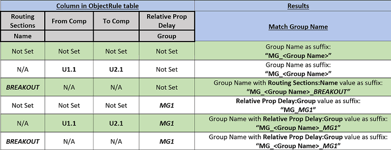
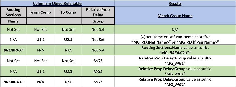
Object Rule Group and Name or Type Classification reference in Xnets or Diff Pairs
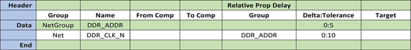
Object Rule table Example (Match Group – From Comp/To Comp Common Target)
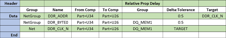
Compiler Results
- Match Group Name MG_DDR_ADDR with Pin Pair members (U34 to U26) of NetGroup DDR_ADDR members and Net DDR_CLK_N in Target column
- Match Group Name MG_DQ_MEM1 with Pin Pair members (U34 to U26) of NetGroup DDR_BYTE0 members and Net DDR_CLK_N with TARGET entered in Delta:Tolerance column.
Object Rule table Example (Match Group – Topology/Routing Sections Common Target)
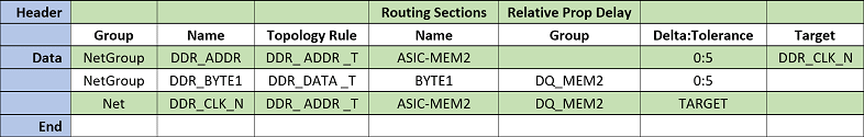
Compiler Results
- Match Group Name MG_DDR_ADDR_ASIC-MEM2 with Routing Sections Pin Pairs of NetGroup DDR_ADDR members and Net DDR_CLK_N in Target column.
- Match Group Name MG_DQ_MEM2 with Routing Sections Pin Pairs of NetGroup DDR_BYTE1 members and Net DDR_CLK_N with TARGET entered in Delta:Tolerance column.
Match Group members with different Delta/Tolerance values
To specify a unique Delta/Tolerance for member(s) inside a Match Group (for example, Clock Diff Pair, Dual Diff Pair Btye lanes) can be done in an Object Rule table by adding a separate row, after the initial Match Group row, to specify the net which requires a different Delta/Tolerance value. This row must include the Match Group name to ensure the updates are made appropriately.
Object Rule table example (Match Group – Clock Net with different Delta/Tolerance):
Compiler Results
- Match Group Name MG_DDR_ADDR with NetGroup DDR_ADDR members will be matched to Delta:Tolerance value
- Net DDR_CLK_N will be added to Match Group MG_DDR_ADDR with the value entered in Delta:Tolerance column, if it is already part of the Match Group it will be updated.
Net DDR_CLK_N must be added after the initial Match Group row to ensure that appropriate Delta:Tolerance is applied.
Object Rule table example (Match Group – 2nd Diff Pair with different Delta/Tolerance)
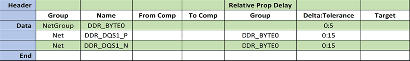
Compiler Results
- Match Group Name MG_DDR_BYTE0 with NetGroup DDR_BYTE0 members will be matched to Delta:Tolerance value
- Nets DDR_DQS1_P and DDR_DQS1_N are already members of Match Group MG_DDR_ADDR but will have the value entered in Delta:Tolerance column
Nets DDR_DQS1_P and DDR_DQS1_N must be added after the initial Match Group row to ensure that appropriate Delta:Tolerance is applied.
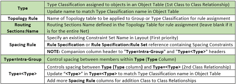
Object Rule table (Class to Class Rules)
The Object Rule table can also be used to create Class to Class relationships between type classifications defined in an Object Rule table. Objects grouped under a type classification are processed and generate the required spacing Net Classes to support the Class to Class spacing requirements. Each type-to-type relationship reference to either a rule specification, rule set or an existing spacing CSet (Spacing Set:<Set Name>) to apply an appropriate rule.
Column Header Description
Sample Object Rule table (Class to Class Rules)
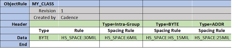
Compiler Results
- Spacing for the group of nets in Type BYTE gets checked to all other nets using rule set 30 mil from the HS_SPACE rule specification
- Spacing for nets contained in Type BYTE (Intra-Group) gets checked to each other using rule set 6 mil from the HS_SPACE rule specification
- Spacing for a group in Type BYTE gets checked to other Type BYTE groups using rule set 15 mil from the HS_SPACE rule specification
- Spacing for each group in Type BYTE gets checked to Type ADDR groups using rule Set 25 mil from the HS_SPACE rule specification
- Rule columns can also reference existing CSets SpacingCSet:<CSet Name>
- A Spacing Net Class with prefix NC_ gets created using the group name defined in Object Rule table
Object Rule table (Region Class/Class-Class Rules)
The Object Rule table can also be used to create Region Class and Region Class to Class relationships between Type classifications defined in an Object Rule table. Objects grouped under a Type classification are processed and generate the required Net Classes to support the Region Class/Class-Class spacing requirements. Each Type-to-Type relationship must reference either a Rule Specification, Rule Specification: Rule Set or an existing CSet so that the appropriate rule can be applied.
Column Header Description
Sample Object Rule table (Region Class to Class Rules) of Region Created in Constraint Manager

Compiler Results:
-
Region CONN_AREA created in Object Rule table generates a region object in Constraint Manager
Region object in Constraint Manager needs to be manually assigned to Constraint Region Shape on the canvas
- Physical constraints checked to all nets entering the region CONN_AREA using rule set 4MIL from the HS_PHY rule specification
- Spacing constraints checked to all nets in the region CONN_AREA using rule set 4MIL from the HS_SPC rule specification
- Physical constraints checked to group of nets in Type BYTE entering the region CONN_AREA using rule set 6MIL from the HS_PHY rule specification
- Physical constraints checked to group of nets in Type ADDR entering the region CONN_AREA using rule set 7MIL from the HS_PHY rule specification
- Spacing constraints for a group in Type BYTE are checked to other Type ADDR groups in the region CONN_AREA using rule set 15MIL from the HS_SPC rule specification
- Type designations result in a spacing net class with a NC_ prefix in layout using the group name defined in Object Rule table
Sample Object Rule table (Region Class to Class Rules) of Existing Region in the Design
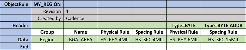
Compiler Results:
- Existing region BGA_AREA in Constraint Manager generates the required class and class to class relationships so that the appropriate Constraint Sets can be assigned
- Physical constraints checked to all nets entering the region BGA_AREA using rule set 4MIL from the HS_PHY rule specification
- Spacing constraints checked to all nets in the region BGA_AREA using rule set 4MIL from the HS_SPC rule specification
- Physical constraints checked to group of nets in Type BYTE entering the region BGA_AREA using rule set 6MIL from the HS_PHY rule specification
- Spacing constraints for a group in Type BYTE are checked to other Type ADDR groups in the region BGA_AREA using rule set 15MIL from the HS_SPC rule specification
- Type designations result in a spacing net class with a NC_ prefix in layout using the group name defined in Object Rule table
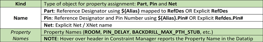
Object Rule table (Properties)
The Object Rule table can also be used to assign Component, Pin and Net properties in design. Using an ACC table provides flexibility to assign related properties to drive interface guidelines alongside constraint definitions such as ROOM, PIN_DELAY, BACKDRILL_MAX_PTH_STUB, and so on.
Column Header Descriptions
Object Rule table (Component Property assignment)
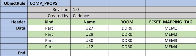
Compiler Results
- ROOM property assignment to drive placement in a particular region in design.
- U27, U29, U30 and U12 assigned a ROOM Property with a value of DDR0.
- Used to drive placement in a particular room defined in design.
- ECSET_MAPPING_TAG property assignment to assist with topology mapping.
- U27 assigned an ECSET_MAPPING_TAG property with a value of MEM1.
- U29 assigned an ECSET_MAPPING_TAG property with a value of MEM2.
- U30 assigned an ECSET_MAPPING_TAG property with a value of MEM3.
- U12 assigned an ECSET_MAPPING_TAG property with a value of MEM4.
- U27 assigned an ECSET_MAPPING_TAG property with a value of VIPER.
Object Rule table (Pin Property assignment)
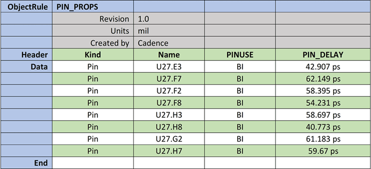
Compiler Results
- PINUSE Bi-Directional (BI) assigned to U27 Pins E3, F7, F2, F8, H3, H8, and G2.
- PIN_DELAY (Pin delays) applied to U27 Pins E3, F7, F2, F8, H3, H8, and G2.
Units keyword in header used to indicate default length units for table. When pin delay value are in time (ns/ps), time measurement values follow the same units (42.907 ps).
Object Rule table (Net Property assignment)
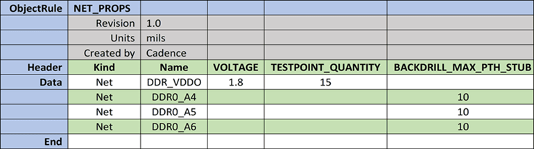
Compiler Results
- VOLTAGE Property with a value of 1.8V assigned to power net DDR_VDDO.
- TESTPOINT_QUANTITY of 15 indicates number of test points for net DDR_VDDO.
- BACKDRILL_MAX_PTH_STUB of 10 indicates maximum stub requirements before backdrilling is required.
XML Constraint Data Schema
A complete data set in an XML format provides executable constraints for common interfaces and integrated chips, such as CPU, SoC, and PCH.The XML data sets are developed in collaboration with IC manufacturers that publish PCB Design guidelines for their chip sets.
Constraint data set can be used directly into Constraint Manager using the Constraint Compiler avoids the need of interpreting and extracting relevant information from PCB guidelines. Using data set saves the time spent in mapping the design data and manual effort of entering into Constraint Manager.
XML Constraint Data Set Format
To create specifications in new format, a corresponding schema (XSD) file is available to validate the structure of the created XML files.
The schema validation files exist in the installation directory at <installation_directory>/share/pcb/consmgr/schemas/ACC_schemas
The following is a list of constraint data set:
| Constraint Data Set | Used for ... |
|
(High level design details) |
Constraint units and Interface references |
|
(Routing topologies |
Topology by Interface, Route Section rules, general constraints |
|
(Interface structure) |
Pin and Net Groups, Match Groups and Diff Pairs |
|
(Physical requirement) |
Differential and Single-ended Impedance physical requirements |
|
(Spacing requirement) |
General spacing and Class to Class spacing requirements |
|
(PCB Cross-Section structure) |
Stack-up for impedance calculations driving physical/spacing requirements Stack-up used as reference by the compiler to verify layer count match |
Constraint Compiler Starter Templates
To assist in table creation, Microsoft Excel spreadsheet (.xlsx) template files are provided as a part of installation. You can copy, modify, and save these tables with new names in your constraint library.
The tables need to be saved in .csv format only using the File – Save As command to be read by the constraint compiler.
The Starter Table worksheet tab contains the default column headers as well as a description of each at the bottom of the worksheet. This worksheet tab is where the table information is entered.
Each template file contains the Data Row Examples worksheet tab that contains sample templates with specific examples based on the type of template file. Rule template files have additional worksheet tabs that provides the different constraint header names for each of the domains (Physical, Spacing, and Electrical).
The starter templates exist in the installation directory at <installation_directory>\share\pcb\examples\acc\Starter_Templates.
Data Table Templates
| Name of Data Table | Name of Template File |
|
Mapping Name Table |
mapping_starter.xlsx |
|
Topology Table |
topology_starter.xlsx |
|
Object Table |
object_grouping_starter.xlsx |
|
Rule Specification Table (Rule Sets) |
For all domains
For Physical domain
For Spacing domain
For Electrical domain
|
|
Object Rule table (Object Rules) |
objectrule_spec_starter.xlsx |
|
Object Rule table (Class to Class Rules) |
objectrule_class_to_class_starter.xlsx |
|
Object Rule table (Region Class/Class-Class Rules) |
objectrule_class_to_class_starter.xlsx |
|
Object Rule table (Component Properties) |
objectrule_Comp_Props_starter.xlsx |
|
Object Rule table (Pin Properties) |
objectrule_Pin_Props_starter.xlsx |
|
Object Rule table (Net Properties) |
objectrule_Net_Props_starter.xlsx |
The starter templates generated as separate files per table type for simplicity and instructional purposes, but can be combined into one file.The Mapping Name Table is the only exception, recommended to remain separate for alias to design specific mapping.
Design Specific Mapping Name Table
Object and Object Rule Table combined in one spreadsheet
View the next document: 08 - Customizing Constraint Manager
If you have any questions or comments about the OrCAD X platform, click on the link below.
Contact Us