08 - Customizing Constraint Manager
Customizing the Constraint Manager User Interface Customizing Worksheets in Constraint Manager How to Customize Constraint Manager Simulations Customizing Design Rule Checks Formulas in Constraint Manager Creating User-Defined Constraints User-Defined Predicates User-Defined Actuals User-Defined Measurements Query Based Rules
Customizing the Constraint Manager User Interface
You can control the user interface of Constraint Manager, including visibility options, user-definable keyboard shortcuts and user-definable toolbars.
Customizing Visibility
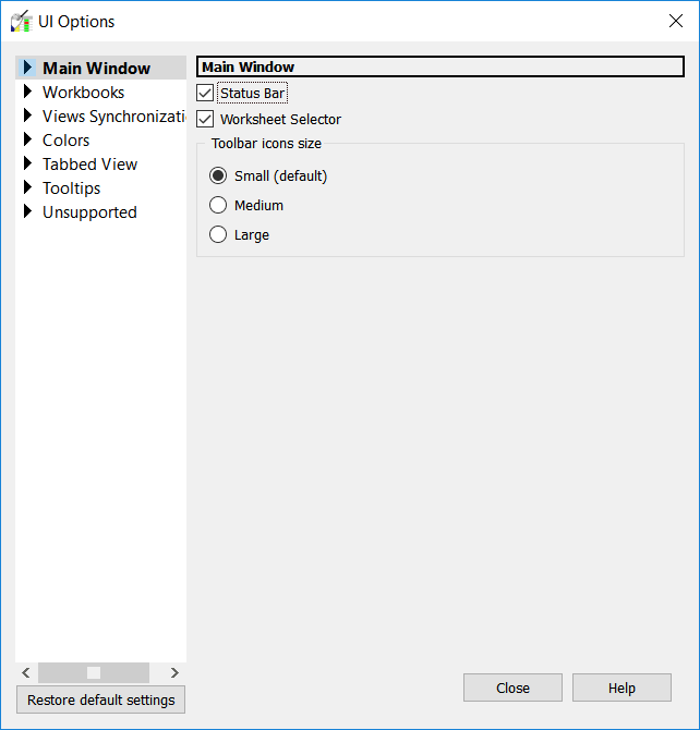
Constraint Manager provides several options to personalize your view of the user interface.
Customizing Toolbars
You can undock the toolbar (or a section of the toolbar) and reposition it in your workspace. You can also rearrange command icons within the toolbar strip and you can create your own toolbar, drawing from existing File, Edit, View, and Filter commands.
Customizing Documentation for User-Defined Attributes
The Information command available on right-clicking a column header, including a user-defined constraint, in Constraint Manager is used to access the associated help information for the selected column. This information describes the purpose of the property or the constraint.
A grayed out information menu command indicates that no documentation exists for the user-defined attribute.
You can create documentation for a user-defined attribute (column) and make it accessible using the following steps:
- Create documentation on the user-defined attribute.
You can capture user-defined documentation in a file with the same name as the attribute. The following file formats are supported:- .html
- .bmp
- .txt
- Save the file as <attribute_name>.<html>/<bmp>/<txt>.
For example, for an attribute named NEW_COL, the help file name will be NEW_COL.html. - Save the file in one of the following locations:
- current directory - along with the .brd file
- <install_directory>/share/pcb/consmgr
- CDS_SITE/cdssetup/consmgr, provided the CDS_SITE environment variable is configured
- In Constraint Manager, right-click the column header of the user-defined attribute and choose the Help command.
The associated help file is displayed on top of the Constraint Manager application.
Customizing Worksheets in Constraint Manager
You can add user-defined or pre-defined attributes to the default worksheets, and you can create your own customized workbooks and worksheets.
PCB Editor uses the term Property, Constraint Manager uses the term Constraint, and Design Entry HDL uses the term Attribute. The term Attribute is used here to describe a Constraint, Property, or Attribute, whether it is validated or not.
Each net-level customized worksheet that you add has an Objects column and a Referenced CSet column (you can hide the latter). Customized worksheets do not contain Actual and Margin columns.
Each attribute that you add to a worksheet requires a new column. New columns appear to the right of the active worksheet. As with overrides, Constraint Manager renders customized workbooks, worksheets, and columns with a blue tint in the Worksheet Selector.
You can add, rename, and delete workbooks, worksheets, column headers and columns, and you can control their visibility. You can also export worksheets that you define, and you can import customized worksheets from a different design. Although you can hide columns of default worksheets, you cannot delete them. Also, you cannot delete predefined worksheets or predefined attributes.
Customize Mode in Constraint Manager
In addition to the Browse mode, Constraint Manager has a Customize mode, which uses special icons in the Worksheet Selector to assist you in differentiating among predefined workbooks, worksheets, and columns from those that you add in Customize mode.
Use the Customize Worksheet command to add user-defined or predefined attributes to Constraint Manager’s default worksheets or create customized workbooks and worksheets. You can also use drag-and-drop to reorder columns.
You can also access the Customize mode by right-clicking in the Worksheet Selector and choosing Customize Worksheet.
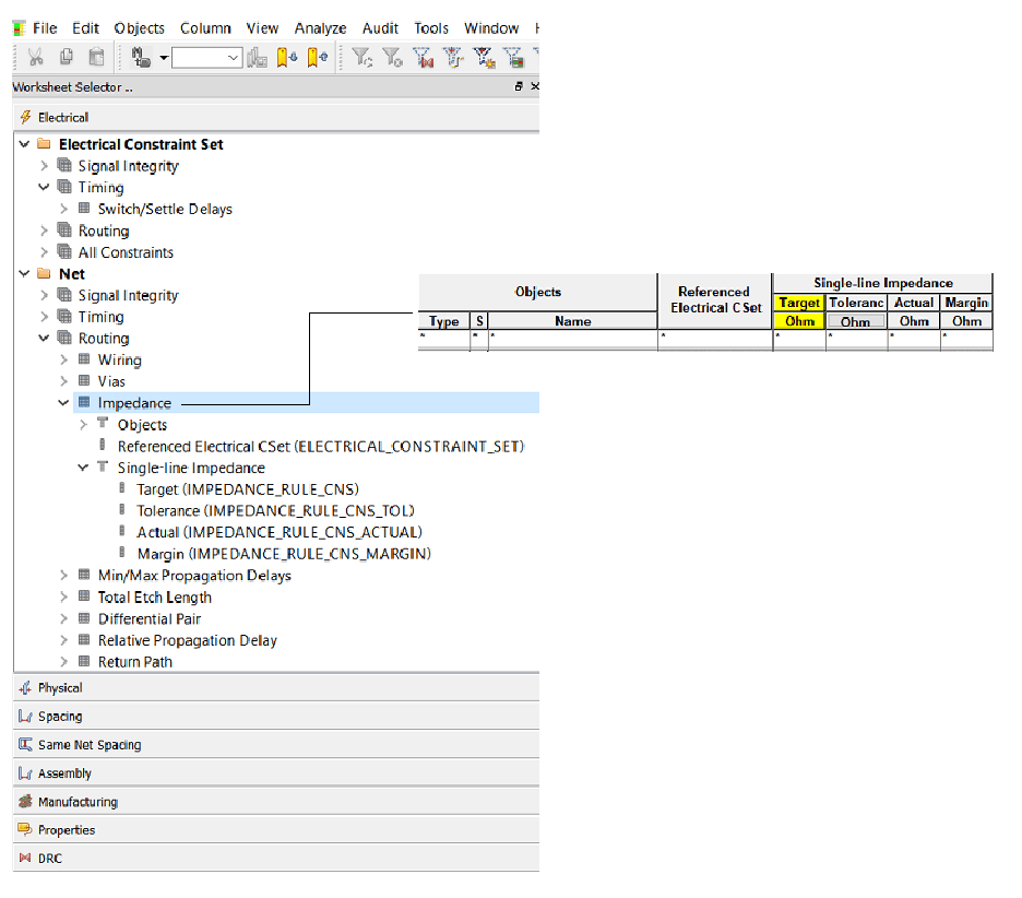
The image Worksheet Selector icons in Customize mode depicts the expanded Impedance worksheet of the Routing workbook. Notice that the default columns have a neutral, grayish tint except for the hidden Referenced CSet column, which is represented by the silhouette of a circle. Also note the column’s superheader label (Single-line Impedance) depicted with a rectangle over a circle.
In the same figure, notice the My Impedance worksheet of the My Routing workbook. The workbook, worksheet, and all columns have a bluish tint. Also note the column’s superheader (My Single Line Impedance).
The columns in the My Single Line Impedance worksheet are the same as those in the Single Line Impedance worksheet except for the difference in column labels: Which Net substitutes for Target and Allowable Deviation substitutes for Tolerance. Also, the Electromotive Force column label identifies the added column for the Voltage attribute.
A column superheader icon appears as a rectangle over a circle; a column icon appears as a circle. A predefined column icon is gray; a customized column icon is blue; a hidden column icon is a silhouette of the column icon.
Worksheet Selector icons in Customize mode
Creating User-Defined Properties
You use a user-defined property to capture a characteristic of an object. Constraint Manager does not perform design rule checks or analysis on this property; it facilitates communication of the design intent to down-stream tools with which you may want to use to work with the objects associated with these properties.
To create user-defined properties, follow these steps:
- Choose Setup - Property Definitions, in PCB Editor or APD.
Or Choose Set - Constraints - User-Defined, in SigXplorer.
The Define User Properties dialog box appears. - Select the property you want to define and configure the options as required.
For Constraint Manager to report or display a user-defined property:
- Navigate to the required net-related worksheet.
- Enable customization with the Tools - Customize Worksheet command.
- Right-click the worksheet in the Worksheet Selector and choose Add Column.
The Add Column dialog box appears. - Choose the user-defined property you want to display in the worksheet and click Apply.
- Click OK to close the Add Column dialog box.
Constraint Manager then adds a column to the far right of that worksheet with the property name as its column label. There are no Actual and Margin cells associated with user-defined properties.
Additionally, the property appears under the Electrical CSet folder, in the User-Defined worksheet (and in the Signal Integrity/Timing/Routing worksheet) of the All Constraints workbook.
You can also create a validated user-defined property directly in Constraint Manager.
How to Customize Constraint Manager Simulations
Constraint Manager supports custom constraints, custom measurements, and custom stimulus when used with the SigXplorer legacy flow.
Constraint Manager, when launched from OrCAD X PCB Editor, does not support custom constraints, custom measurements, or custom stimulus. The Custom Measurements tab in the Analysis Modes dialog box (choose Analyze - Analysis Modes) as well as the Custom Measurements workbook is hidden.
You do not define custom constraints, custom measurements or custom stimulus in Constraint Manager, you only assign, manage, and analyze them. You define them in SigXplorer, save them as a topology file, and import them into Constraint Manager as an Electrical CSet (Choose File - Import Electrical CSet) or refresh the current Electrical CSet reference (Choose Tools - Update Topology). Any net-related object that references that Electrical CSet inherits any custom constraint, custom measurement or custom stimulus data that was captured in that Electrical CSet.
By default, custom measurements are not included with an imported Electrical CSet. To override this behavior, you must enable the Update existing or create new Custom Measurement worksheet option. See the File - Import - Electrical CSets command: Use this command to import a selected on-disk topology template into Constraint Manager. The imported template becomes an Electrical CSet, which can be referenced by net-related objects that share the same electrical characteristics. An Electrical CSet is a named collection of electrical constraints and their default values.
Not only does An Electrical CSet contain pre-defined and custom constraints, and it can also contain custom measurements and custom stimulus.
Because you can assign only a single Electrical CSet to a net-level object, you must define any constraint data along with custom measurement and custom stimulus in that same Electrical CSet.
Working with Custom Constraints
In addition to its broad set of pre-defined constraints, Constraint Manager supports constrained custom measurements.
Constrained Custom Measurements
You use constrained custom measurements (and custom stimulus) to specify your own constraints. These constraints differ from user-defined properties in that Constraint Manager can validate them through design rule checks and analysis.
You create constrained custom measurements in SigXplorer in the same way as you define unconstrained custom measurements, using the measurements expression editor. When you choose None as the constraint type, SigXplorer creates an unconstrained custom measurement. When you choose minimum, maximum, min-max, or target: tolerance as the constraint type, SigXplorer creates a constrained custom measurement, which is, in effect, a user-defined constraint.
To invoke SigXplorer’s Measurement Expression Editor
- Click the Measurements tab
- Right-click on the Custom tab, and
- Select Add.
Constrained custom measurements from SigXplorer appear under the Electrical CSet folder, in the User-Defined worksheet of the All Constraints workbook, as well as under the Net folder in the Custom Measurements workbook (see the image Custom Measurements in Constraint Manager#59671User-defined Constraints and Custom Measurements). Actual and Margin cells associated with constraint also appear.
Extracting Constraints from SigXplorer
Follow these steps to extract constraints from SigXplorer:
- Select a net object in Constraint Manager.
- Right-click and choose SigXplorer from the pop-up menu.
The net’s topology will appear in SigXplorer where you define the necessary custom constraints, or custom measurements and custom stimulus. -
Choose File - Update Constraint Manager to export the topology file from SigXplorer.
The corresponding Electrical CSet is refreshed in Constraint Manager and all net-related objects that reference the Electrical CSet will inherit the custom constraints or custom measurements and custom stimulus that you just defined, along with any electrical constraints that were captured in the Electrical CSet before they were exported from Constraint Manager to SigXplorer.
If the object that you extracted from Constraint Manager into SigXplorer does not reference an Electrical CSet, when you choose File - Update Constraint Manager from SigXplorer, the topology file is imported into Constraint Manager as an Electrical CSet with the same name as the extracted object, unless you chose File - Save As. You can then associate that Electrical CSet with other net objects (choose Objects - Electrical CSet Reference), and rename the Electrical CSet if you want to (choose Objects - Rename).Constraint Manager retains the analysis modes settings that you define in the Electrical CSet when you export the topology to SigXplorer.
Custom Measurements in Constraint Manager
After they are defined and imported from SigXplorer, custom measurements and constrained custom measurements populate an Electrical CSet under the Custom Measurements workbook in the Net folder. Each set of custom measurements or constrained custom measurements (an Electrical CSet) appears as an individual worksheet. Each custom measurement appears as a column in the worksheet.
User-defined Constraints and Custom Measurements
Constraint Manager maintains custom measurement and custom stimulus associations--Electrical CSet to object--as well as analyzed results from one session to the next.
When you select an Electrical CSet in the Referenced Electrical CSet column of the Custom Measurements worksheet, and then right-click and choose SigXplorer from the pop-up menu, that Electrical CSet is exported from Constraint Manager to SigXplorer as a topology with custom measurements and custom stimulus intact. Choosing File - Update Constraint Manager from SigXplorer then refreshes the custom measurements in Constraint Manager with any changes.
Analyzing with Custom Measurements and Custom Stimulus
The flow that you must follow to analyze custom stimuli is as follows:
- Import an Electrical CSet that contains custom measurements.
- Assign the ECSet to a net object.
- Specify analysis settings.
- Enable custom measurements.
- Run the analysis.
Analyzing a net-related object with a custom constraint or custom measurement involves the same steps as described in analyzing constraints. Additionally, you must follow these steps:
- Specify Analysis Settings
Specify the simulation type in the Analysis Settings dialog box. If you have custom stimulus defined in the Electrical CSet, it too must be enabled for analysis.
Custom measurements apply only to reflection simulations. -
Enable Custom Measurements
Enable custom measurements through the Custom Measurements tab of the Analysis Modes dialog box (choose Analyze - Analysis Modes). Measurements appear as children in a tree structure with the parent object representing the Electrical CSet that contains the set of custom measurements.When Constraint Manager is launched from OrCAD X PCB Editor, it does not support custom measurements or custom stimulus.
The check box adjacent to the parent object also serves as a toggle switch for all measurements in the Electrical CSet: all on (when checked) or all off (when unchecked). Only checked measurements appear in analysis results.
- Analyze Custom Measurements
Choose Analyze - Analyze.
Alternatively, right-click and choose Analyze from the pop-up menu.
You do not analyze a custom constraint or custom measurement; rather, you analyze the object that references an Electrical CSet which contains custom constraints or custom measurements.
The scope of a net object that contains a custom measurement can range from a pin-pair to a bit of a bus to an entire bus.
Customizing Design Rule Checks
This section presents different methods used to customize Design Rule Checks (DRCs), including:
- Formulas
- User-defined Constraints
- User-defined Predicates
- User-defined Measurements
You can choose from pre-defined predicates and pre-defined measurements or you can create your own to address your unique design requirements.
Formulas in Constraint Manager
To meet your unique constraint requirements, you can extend constraints and properties (pre-defined and user-defined) with formulas. A formula is required when a static value is not sufficient and a relatively simple calculation is required to compute the desired constraint or property value.
You can build a formula using the following methods, alone or in combination:
- Cell selection, mixed with operands
- Pre-defined and user-defined predicates
- Programatically, with the Cadence SKILL scripting language
Each method of defining a formula is progressively more complex, yet yields more power and flexibility in using them to constrain your design.
Inserting a Formula in a Cell
Follow these steps to insert a formula in a cell:
- Select the cell you want to insert the formula in.
- Right-click and choose Formula from the pop-up menu
Alternatively, choose Edit - Formula. This invokes the Single-line Editor, as shown in figure Single-line Editor. - Here you can insert a formula into the cell in a number of ways.
- Manually type in the formula in the Set formula field.
- You can use the Multi-line Editor to define the formula.
- If you’ve already defined a formula using the Multi-line Editor, you can reuse it and subsequently edit it as required. Constraint Manager remembers which editor you last used in building a formula. For easy identification, Constraint Manager renders the far end of a cell that contains a formula with a thin, red, vertical stripe.
The Single-Line Editor
You use the Single-line Editor to build simple formulas, which may contain user-defined constraints, properties, and predicates.
In the figure below:
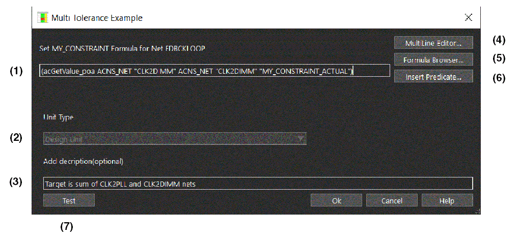
- Item (1) is where you type in your formula. You can use point-and-click to add cell addresses to the formula.
- Item (2) is the Unit Type, which varies depending on the cell being modified by the formula.
- You enter a description of the formula in Item (3).
- Item (7) exercises the formula. You should always test your expressions for proper syntax and function.
- Item (4) launches the Multi-line Editor used to create formulas.
- Item (5) is the formula browser where you can access existing formulas and leverage them for use elsewhere in the design.
- Item (6) is for adding predicates to the formula.
Single-line Editor
The Formula Browser
You can view all the formulas in the design and assign them to specific cells in the Formula Browser window.
Cell Selection and Operands
The cell selection and operand method provides for point-and-click cell selection, mixed with operands to build a formula. Clicking within a cell adds the code required to access that cell in the formula. For example, (acGetValue_o ACNS_NET "CLK2PLL")+5 results from selecting a cell for an another object in the worksheet, in the same column as the one selected for Formula editing, and then typing +5.
Cell selection automatically inserts the appropriate predefined predicate to get the value for the selected cell. The inserted predicates will differ based upon what information is needed to retrieve the value. For example, the same object in a different cell only needs the name of the cell's attribute because the object being edited is considered the default object.
Calculating a Formula
Constraint Manager keeps track of a formula's dependencies on other cells or database objects. For example, the value in a cell or the etch length of a net. When one of those dependencies changes, the formula is known to be out of date or stale. Out of date formulas recalculate their new values as needed.
- Choose Edit - Calculate
-OR-
Choose Edit - Calculate All to bring any out of date formulas back up to date.
You can review or modify the dependencies using the Dependencies dialog box (choose Edit - Dependencies).
Pre-Defined Predicates
Predicates are functions that return data (usually a single value). They work to access design information to enhance the functionality of formulas, other predicates, and measurements. You can choose from predefined predicates and create your own.
Use the Edit – Formula command to customize any property or constraint by adding a formula. You do not have to be in worksheet customization mode to use formulas.
User-defined predicates and measurements are closely related to formulas, but they do not have menu choices; therefore, much of the material in this section applies to them as well.
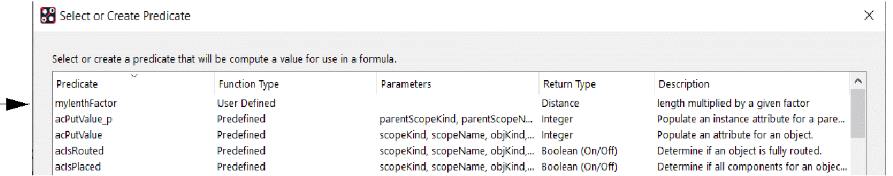
You access the Select or Create Predicate dialog boxby clicking Insert Predicate (see Item 6 in the The Single-Line Editor figure.
Select or Create Predicate dialog box
See Predicate Parameters for column definitions.
Programmatic Formulas
The Multi-line Editor (see the The Single-Line Editor Single-line Editor figure) provides the maximum flexibility when adding programming constructs to formulas.
The top of the Multi-line Editor shows the description of the formula and the list of parameters. The formula that you are building appears at the bottom of the window.
To use the multi-line editor to build and use custom formulas, follow these steps:
- Select Multi-line Editor in the Single-Line Editor dialog box.
- Type in the Multi-line Editor to build your formula. Common editor functions, such as Copy and Paste, are selectable from the context menu (right-click).
- Assign each predicate to a variable and wrap the formula in a let statement.
The let statement also protects the variables from being influenced by global access.
- From the menu, choose File - Test.
Choosing this menu item is the same as clicking the Test button in the lower-left corner of the main Formula (single line) dialog box.
There are four main sections in the Formula Test dialog box:- A listing of the Formula itself.
- A debug message section, which is currently blank.
- The formula result. In this case, verify that 3498.44 is the expected result.
- SKILL LINT output to further check the SKILL code for possible errors.
- Close the Formula Test dialog box.
- Close the Multi Line Editor window and click Save if prompted.
- Assign the formula to the required cell.
- Choose Edit - Calculate OR Choose Edit - Calculate All.
Support for Online Formulas
Constraint Manager determines and stores dependency information of all the Advanced Constraints formulas as they are created or loaded for the first time. The dependency information is stored with the formulas such that a formula is not recreated each time the design is closed and reopened.
Dependency information is used to update the status of calculated values and indicates when they become stale.
Some cases where calculated values can become stale (out of date) are:
- A formula on a cell that references the value in another cell.
- A formula that calls a predicate that returns some information about a database object.
When values are changed in Constraint Manager, or if database objects are updated in PCB Editor, Constraint Manager determines which values are out of date, and recalculates them when necessary.
Launching Constraint Manager marks all the formulas stale. This is indicated by coloring the formula cell with yellow. When you run Calculate on a stale cell, the cell value is updated and cell color is cleared. If you run Calculate All, all the cells in all worksheets are updated and the yellow color is cleared.
Testing and Debugging Formulas
You can use the Constraint Manager test environment to debug formulas. In a debug session, Constraint Manager temporarily makes changes to the database; however, these changes are not saved when you exit the test environment.
You enter the test environment from the:
- Multi-line Editor (choose File - Test)
- Single-line Editor (click Test). See Item 7 in the Single-line Editor figure.
Formula testing produces a log file similar to the log file used for testing user-defined predicates and user-defined measurements (see the Testing and Debugging User-Defined Predicates Functional test output figure).
Constant Manager supplies many pre-defined predicates (look for acDebug_print*), which you can use to debug your formulas.
Creating User-Defined Constraints
In addition to its broad set of pre-defined constraints, Constraint Manager lets you define constraints to meet your unique design requirements. A user-defined constraint is required to capture a unique design requirement, which is not represented in the default constraint system. User-defined Constraints also specify how to validate a new column.
Unlike pre-defined constraints, user-defined constraints analyze only within Constraint Manager and not in a PCB or package editor.
Using the Allegro X PCB Designer Plus license:
- Launch Constraint Manager.
- In the Worksheet Selector pane, choose the Electrical domain, right-click on the Net folder, and choose Customize Worksheet to enter Customize mode.
- Right-click on the Net folder again, and choose Add New Workbook.
- Open the associated New Worksheet by double clicking on it in the Worksheet Selector pane.
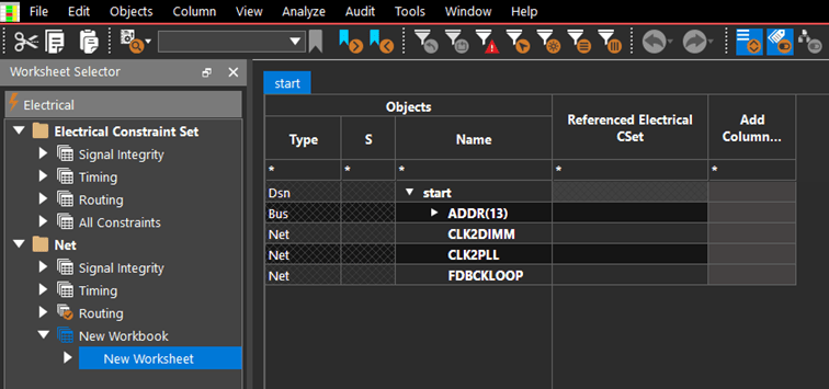
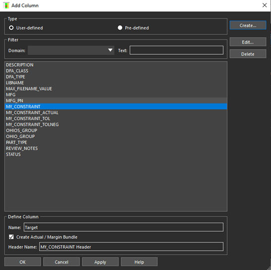
- Click Add Column header in the New Worksheet.
- In the Add Column dialog box, leave the Type field set to User-defined, and click the Create button.
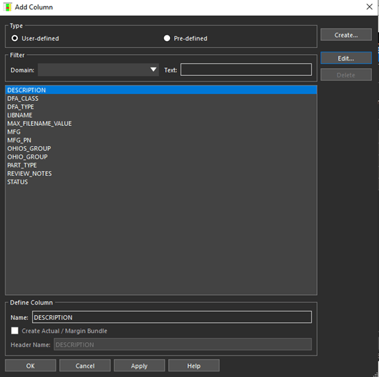
- Property specifies a user-defined property.
- Min Constraint, Max Constraint, Target +/- Tolerance, Target/Tolerance specifies a user-defined constraint, and a corresponding Actual and Margin.
- Target/Tolerance allows for separate plus and minus tolerance values.
- Target +/- Tolerance allows for a single tolerance value.
- Actual specifies a single column that is linked to a measurement and used to display the measurement results. An Actual value can be part of a user-defined constraint.
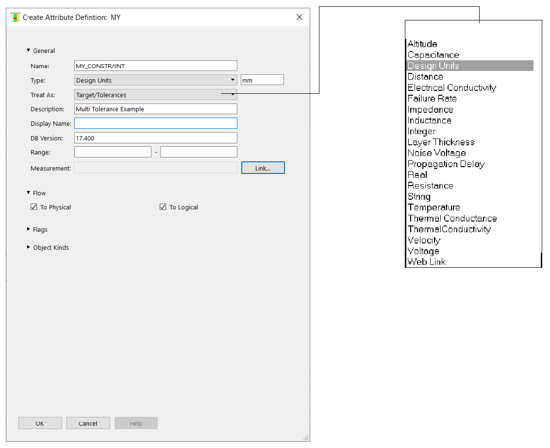
- Complete the Create Attribute and Create Attribute Definition dialog boxes as shown below.
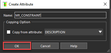
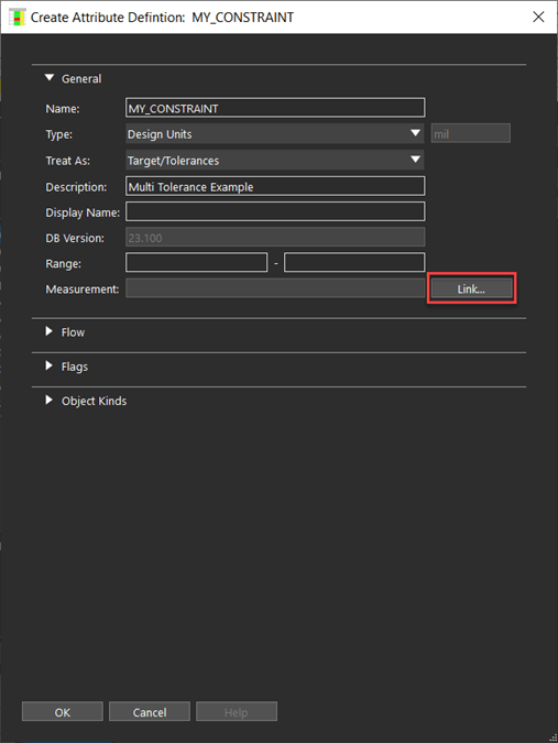
Make sure that there are no spaces in the Name field and set the Data Type to Design Units.
The Treat As list in the Create Attribute Definition dialog box is where you specify the new user-defined attribute’s type. This can be a property, a constraint, or an actual.
Set the Treat As drop-down list as shown. Leave the Objects and Flag fields as is. The Range field is used in cases where the legal values for a constraint need to be defined.
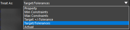
Since different plus and minus tolerance values are required for this example, choose Target/Tolerances. -
Click Link associated with Measurement field.
This launches the Select or Create Measurement dialog box. The choices listed are based on the Type that you chose in the Create Attribute Definition dialog box. At this point, there are no user-defined measurements, so the dialog box lists the supplied pre-defined measurements.It is possible that this dialog box does not list any measurements based on the Type you previously set.
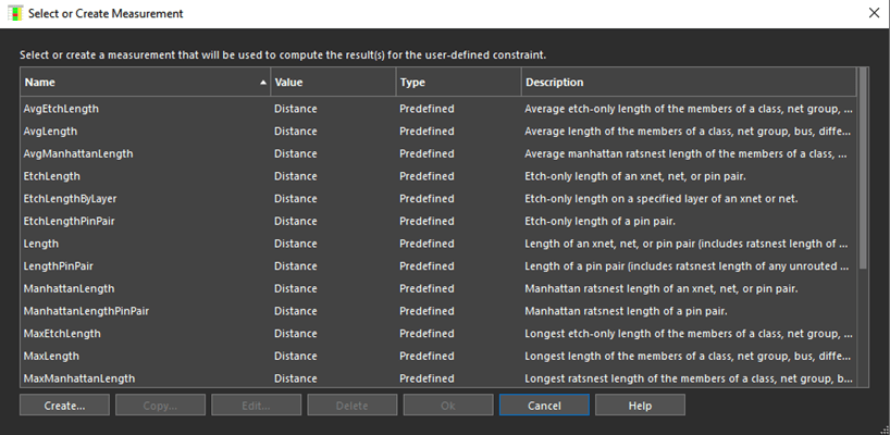
Notice that the Copy, Edit, and Delete buttons are grayed out, even after selecting a measurement. These buttons apply to user-defined measurements only.
- Choose a constraint from the list and click OK.
- Click OK in the Create Attribute Definition dialog box.
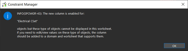
- In the Add Column dialog box with the new columns added and the bottom of the dialog box updated, click OK.
- Click OK if any confirmer dialog box appears.
- In the new column, add some constraint and tolerance values to the affected nets.
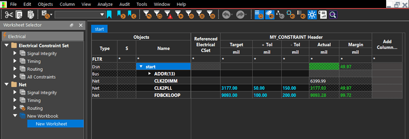
- Right-click the design name (start) in the Objects column, and choose Analyze or press F9.
Notice in figure above that the measurement (Actual) is calculated even if the Object is not constrained. This is true for all the added user-defined Actuals (whether or not they are part of a user-defined constraint).
You may notice that there is no DRC in PCB Editor to indicate this situation. At this point, Pass / Fail status is indicated in Constraint Manager only.
Deleting User-Defined Measurements
The Copy, Edit, and Delete buttons are enabled only for user-defined measurements.
- Select a user-defined measurement in the list, and click the Delete button.
A warning message appears about some Actuals which may no longer analyze correctly. If you select OK, the measurement is deleted from the list.
The list of measurements is based on the Data Type field in the Create Attribute Definition dialog box. If the pre-defined measurements are not what you need, you can create your own.
User-Defined Predicates
Constraint Manager has many pre-defined, readily-usable, predicates and measurements and it provides the capability to augment them with predicates and measurements that you build to meet your unique design requirements. Predicates function as the building blocks of Formulas, Measurements, and other Predicates.
Predicates are functions that return data (usually a single value). They work to access design information to enhance the functionality of formulas, other predicates, and measurements.
Predicates are more flexible than formulas or measurements. You can define any parameters in any order and have any return type that you want. When you use a predicate you have to match its use to its definition--all parameters have to match the definition and its return value must be appropriate for the object type.
You can write a simple predicates to:
- sort a list of numbers
- find the smallest number
- open, close, or write to a log file
- perform an algebraic calculation
You can write a complex predicate to:
- determine the overlap of two physical objects
- return the distance of an object to a plane
- return a list of database objects that match a specific criteria
- find the closest via to a cline
Predicates can be created using both formulas and user-defined measurements. After you add a formula, choose Insert Predicate (see Item 6 in the The Single-Line Editor#59280Single-line Editor figure).
- In the Select or Create Predicate dialog box, choose Create.
The Setup for User-Defined Predicate dialog box is displayed, as shown in the figure: Defining a predicate.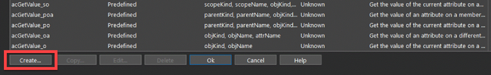
Defining a Predicate
To define a predicate, follow these steps:
- Open the Select or Create Predicate dialog box from the single-line or multi-line editor dialog box.
- Click Create.
The Setup for User-Defined Predicate dialog box appears. - In this dialog box, enter a name, a description, a list of parameters, and a return type (boolean, integer, real, or text). Parameters are the conduit between a predicate and a formula (see Predicate Parameters).
Defining a predicate
Once you complete all fields and click OK, the Multi-line Editor appears with the newly created predicate open.
Editing a predicate
Once you code and save your predicate, the Select or Create Predicate dialog box appears with your new predicate, ready for future use.
Predicate Parameters
A formula contains parameters that are automatically filled in with information about the cell that contains the formula. A predicate also has parameters, often of the same name and function as those in formulas.
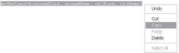
If you want to use a predicate to get information about the current cell, you can just use these parameters as is in the predicate call:
acGetLength(scopeKind, scopeName, objKind, objName)
If you want to use a predicate to get information about other objects, you can substitute the predicate parameters with other values.
scopeKindparameters includeACNS_SYSTEMandACNS_DESIGNscopeNameparameters are strings containing the name of your system or one of the designs in it
Substitute scopeKind and scopeName together to indicate which design or system you want to reference to find your object. If you are not using Design Links, you do not need to define these objects.
Substitute the objKind parameters to specify the type of the object you are referencing. These include:
ACNS_NULLACNS_SYSTEMACNS_DESIGNACNS_XNETACNS_NETACNS_REGIONACNS_ECSETACNS_CLASSACNS_DIFFPAIRACNS_BUSACNS_PINPAIRACNS_MATCHGROUPACNS_RESULTACNS_PCSETACNS_SCSETACNS_CLASS_CLASSACNS_REGION_CLASSACNS_REGION_CLASS_CLASS
Use ACNS_NULL when you do not want any objects, such as a substitute for the parent object.
Substitute the objName parameter to specify a string containing the name of the object. Substitute the attrName parameter to specify a string containing the name of an attribute.
Examples of Predicate Parameters
| Requirement | Predicate Call |
|---|---|
|
To find the length of a system-level Xnet in your formula |
|
|
To find the length of the current object You do not have to substitute the parameters, as they are substituted automatically based on the current object row |
|
|
If you have a formula on NET1 and you want the length of NET2 |
|
|
If you have a formula on NET1 in DESIGN1 and you want the length of NET1 in DESIGN2 of the active System |
|
|
If you have a formula on NET1 in DESIGN1 and you want the length of XNET2 in MYSYSTEM |
|
Testing and Debugging User-Defined Predicates
You use the Constraint Manager test environment to debug user-defined predicates and user-defined measurements. In a debug session, Constraint Manager temporarily makes changes to the database, based on the parameters that you supply. These changes are not saved after you exit the test environment.
- Choose File - Test to enter the Test Environment from the Multi-line Editor.
- Specify parameter VALUES.
The Test Select Parameters dialog box appears. It lists all the parameters that you defined when you set up the predicate. -
Click on a parameter NAME.
A pop-up window appears, and is based on the parameter TYPE (Boolean, Integer, Real, Text).Constant Manager supplies many pre-defined predicates (look for acDebug_print*), which you can use to debug your user-defined predicates.
Test Select Parameters dialog box
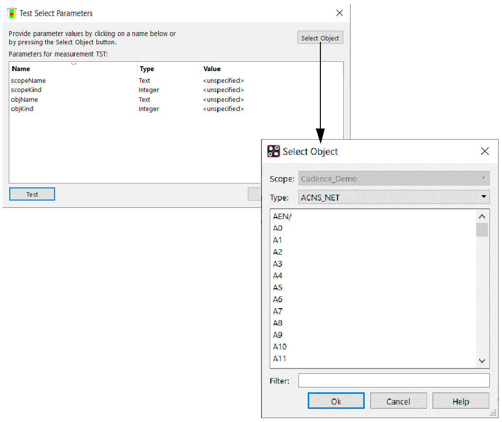
-
In the Test Select Parameters dialog box, select any object in the Select Object window, and information about this object is used to automatically populate the corresponding parameters.
For measurements, this will populate all visible parameters. For predicates, any parameters with the same name as the measurement parameters are populated. -
Click OK.
The Test Select Parameters dialog box returns with as many values as possible, updated automatically.
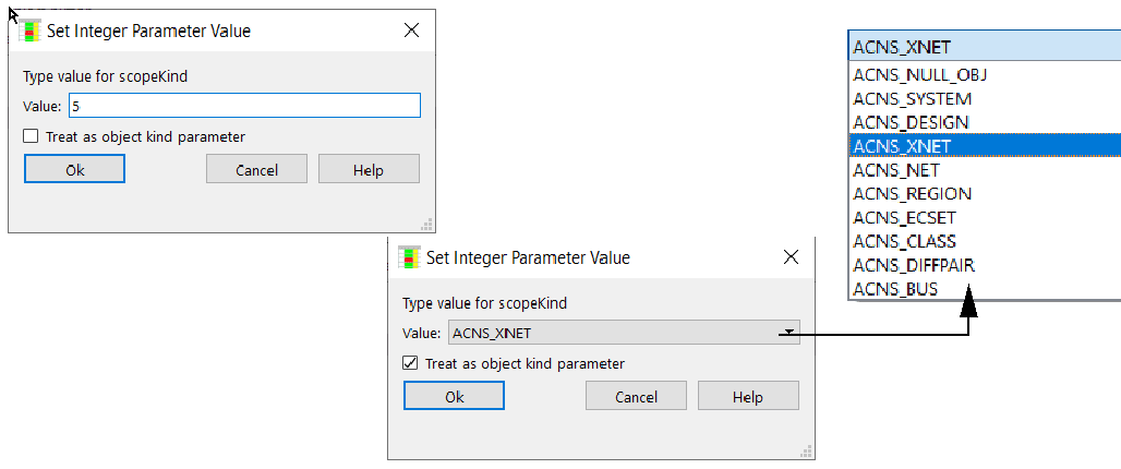
Boolean-, Real-, and Text-parameter TYPEs accept a VALUE that you enter directly; Integer parameter TYPEs accept a direct VALUE when the Treat as object kind parameter is unchecked. If checked, you are presented with a list of all parameter TYPEs in the design.
Parameter values by integer and by object kind
- Once all parameters are specified in theTest Select Parameters dialog box, click Test.
A debug window appears with metrics of the test, including the name of the function, calculated results, return value, and LINT parsing.
Functional test output
You can continue to test the predicate by supplying new or different parameters, and values, in the Test Select Parameters dialog box (see Figure: Test Select Parameters dialog box).
When you click Close in the Function Test dialog box (see Figure: Functional test output), then the Test Select Parameters dialog box, you exit the Test Environment and return to the Multi-line Editor (see Figure: A user-defined Predicate with debugging statements).
A user-defined Predicate with debugging statements
User-Defined Actuals
A user-defined Actual is an attribute that is associated with a measurement. When Constraint Manager analyzes the Actual, the measurement is triggered and the cell that contains the Actual is populated with results.
A user-defined Actual:
- is a term used interchangeably with the term Measurement
- displays the results of a measurement
- can occupy a user-defined column to facilitate custom reports
- can be used in defining a user-defined constraint
You must add a column to a worksheet to accommodate an Actual cell.
The measurement is coupled with the Actual and used when the constraint associated with the Actual value is analyzed.
The measurement is run for the object being analyzed and typically returns results (Actual values) for the same.
After the new column is in place, the Create Attribute Definition dialog box appears (see Figure: User-Defined Measurements#60265Measurement attribute definition (Treat As equals Actual)). Note that Actual is selected from the Treat As list.
-
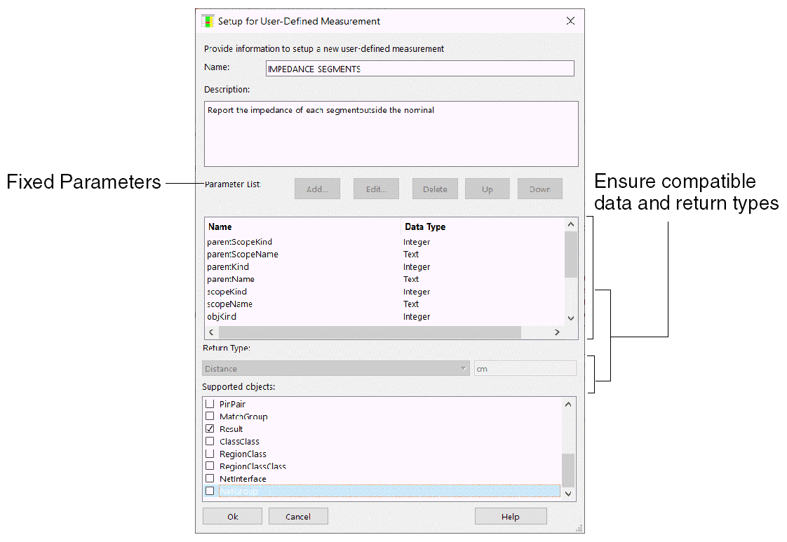
Complete the Setup for User-defined Measurement dialog box as shown in the Figure: Setting up your measurement. Specify a name, a description, and supported objects.
The Parameter List is fixed and the buttons are inactive for user-defined measurements. This dialog box is also used to set up user-defined predicates.
User-Defined Measurements
A user-defined measurement is required to compute a unique result, which is needed to validate the design intent. It requires a new column and it governs how to calculate the results of the new column.
Measurement attribute definition (Treat As equals Actual)
User-defined Measurements:
- have a fixed set of parameters, which are populated by Constraint Manager upon analysis.
- are based on data types, such as design units, as defined in the Data Type list.
- are based on supported object. Actuals calculate for rows that contain supported objects.
- return ACNS_OK to indicate successful completion; ACNS_FAIL to indicate errors.
Setting up your measurement
Once completed, click OK. The Multi-line Editor appears. For information on using the Multi-line Editor.
A User-defined measurement
When defining a measurement:
- Use one of the acPutValue() predicates to populate the Actual. The Actual is passed into the measurement through the actualName parameter.
- If the measurement cannot compute a result, populate the verification status with the reason using acPutValue() predicate, with an ACNS_STRING_TYPE. The verification status is passed into the measurement through the vstatusName parameter.
- If the measurement needs to create a new result object to display under the object being measured, the following predicates are required:
- acCreateResultName to create the name of the new object
- acAddResult to associate the new object with the object being analyzed
- acPutValue to populate the actualName on the new object
-
When you are done with defining the measurement, Save and Close the Multi-line Editor. The new measurement is available for selection.
A measurement returns a status to the calling function, not a calculated value: ACNS_OK upon success; ACNS_FAIL upon getting an error. Calculated values populate an Actual cell using the acPutValue predicate in the body of the measurement. Actual cells are typically populated for the current object or for result objects created by the measurement using the acCreateResultName and acAddResult predicates.
- After you dismiss the remaining dialog boxes, right-click the new column head and choose Analyze from the pop-up menu. This yields results for the new Actual cell with the measurement that you just defined.
Testing and Debugging User-Defined Measurements
Most parameters for user-defined measurements are determined from the object row that is being measured; however, because a measurement can be applied to more than one row, this information is not known when the measurement is being created or edited. A set of values for the parameters must be provided before the measurement can be tested.
Constant Manager supplies many pre-defined predicates (look for acDebug_print*), which you can use to debug your user-defined measurements.
All measurements require the following, fixed set of parameters:
parentScopeKindparentScopeNameparentKindparentNamescopeKindscopeNameobjKindobjNameconstraintNameactualNamevstatusNameverifyMode
When running the measurement, the last four parameters are always the same; therefore, you do not need to specify them.
Some of these parameters can be determined by Constraint Manager, or they are always the same when running the measurement. These parameters do not need to be specified and will not appear in the parameter list in the Test Select Parameters dialog box. Only the scopeKind, scopeName, objKind, and objName parameters need to be specified
All measurements include one of the following TYPE parameters:
ACNS_DOUBLE_TYPEACNS_STRING_TYPEACNS_ENUM_TYPEACNS_INTEGER_TYPEACNS_LONG_TYPEACNS_DOUBLE_ARRAY_TYPEACNS_STRING_ARRAY_TYPEACNS_ENUM_ARRAY_TYPEACNS_INTEGER_ARRAY_TYPEACNS_LONG_ARRAY_TYPE
The TYPE parameter indicates how the calculatedValue parameter is stored in the attribute named by the actualName parameter. Enum types are treated as strings and must be a legal value for the actualName. Array types are lists of values used to populate attributes that contain multiple values (colon separated strings).
The Test Environment for debugging user-defined measurements is identical to that of user-defined predicates.
Query Based Rules
A Query Based Rule (QBR) is a custom constraint rule that you create for HDI vias. You can define two sets of vias using queries and then use the options in the Query Based Rules - HDI Vias worksheet to define constraints for the specified vias.
Available in Allegro X PCB Editor when either the Enterprise PCB Designer Suite or the Allegro X Venture license option is selected. Available in Allegro X Advanced Package Designer when either the Silicon Layout or the SiP Layout option is selected.
Example
You can create a query based rule to specify that two vias which do not share the same layer span and are not connected by a cline need to have larger pad to pad spacing.
View the next document: 09 - Appendix A: Retaining Electrical Constraints at Net Level
If you have any questions or comments about the OrCAD X platform, click on the link below.
Contact Us