02 - ECSets and Topology Templates
Overview
A topology template file (.top) is an on-disk image of the SigXplorer database. A topology template file contains the same data as an ECSet, including electrical constraints, but it also contains information to support the graphical representation of a circuit topology in SigXplorer.
With Constraint Manager, constraint information remains intact, collectively, as an ECSet. Net-related objects in the design reference the ECSet rather than a collection of individual properties.
The topology template can be imported to, and exported from, Constraint Manager. When imported, the topology template information will be instantiated within Constraint Manager as an ECSet where it can be manipulated separate from the topology template. The ECSet is saved with the database of the host application from which Constraint Manager was
invoked: a board file (.brd) or a schematic view.
Topology Template/ECSet constraint flow

With such a close alignment between a topology template and an ECSet, you can access SigXplorer directly from Constraint Manager. In fact, you can define your constraints in SigXplorer—as a topology template—and then import this information into Constraint Manager as an ECSet. Conversely, you can define your constraints in Constraint Manager—as an ECSet—and then export this information to SigXplorer as a topology template.
The only constraint that you cannot define in Constraint Manager is user-defined pin scheduling. This must be defined in SigXplorer. You can, however, select from a list or pre-defined pin schedules in Constraint Manager.
Importing ECSets
You can import a selected on-disk topology template into Constraint Manager. The imported template becomes an ECSet, which can be referenced by net-related objects that share the same electrical characteristics.
To reuse Electrical CSets in Constraint Manager, do the following:
- Choose the File – Import – Electrical CSets menu command.
If the imported template was previously assigned as an ECset, the import overwrites existing constraint values.
If the Automatic Topology Update check box is enabled (Tools – Options), the refreshed template information is immediately applied to the net-related objects; otherwise, you must choose Tools – Update Topology to apply the changes.
Exporting ECSets
You can export a dictionary and constraints file (.dcf) to disk. The dictionary and constraints file contains a complete snapshot of all the electrical constraint information. This includes any user-defined properties, all ECSets and their constraints, and all the net-related objects and their constraints (including ECSet references). The .dcf file is not available for editing.
You can save to a .dcf file prior to modifying constraints within Constraint Manager. The dictionary and constraints file is then considered an archive which can be used to revert to the original state.
Exporting a dictionary and constraints file results in overwriting constraint data saved from an existing archive.
- Choose File – Export – Constraints
OR - Choose File – Export – Electrical CSets, if you want to save only selected ECSets from a design, or from a system, to a topology template (.top) file on disk
Mapping Templates and ECSets to Net-related Objects
Constraint Manager maps the constraint information imported from a topology template or defined in an ECSet to a candidate net that matches the topological characteristics of the referenced ECSet. If the net does not match these topological characteristics, the mapping fails and the constraints are not applied.
- Choose Tools – Options to control how constraints are applied to objects Constraint Manager.
- Use this command to specify options that govern Electrical CSet application. This displays the Options dialog box.
The Options dialog box is displayed. Here, you can specify how the ECSets should be applied.
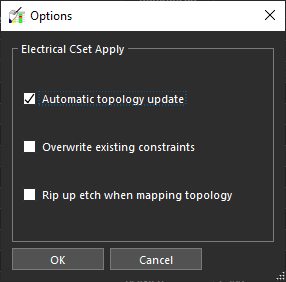
| Check box Option | Function |
|---|---|
|
Automatic topology update (Defaults to selected) |
Controls how topology-related constraints are re-applied
When selected, Constraint Manager applies changes on-the-fly as the design changes. When deselected, you can apply changes by choosing If you change state from deselected to selected, Constraint Manager displays a message confirming that the stale nets and Xnets will be refreshed with updated topology data. Deactivating automatic topology update may be necessary when design changes are frequent and complex ECSets are referenced. |
|
Overwrite existing constraints (Defaults to disabled) |
Controls whether constraint values in the ECSet will overwrite any existing net-related constraints when an ECSet is re-applied. |
|
Rip up etch when mapping topology (Defaults to disabled) |
Controls whether etch (clines and vias) is removed when an ECSet is re-applied and the schedule of the net changes. |
Constraint Manager Audits
Constraint Manager provides feedback in the form of a report about the constraints and their references in the design. Audit commands are available when Constraint Manager is invoked from a layout or design entry editor. The following audits (accessible from the Audit menu) relate to ECSets.
| Run this audit | To |
|
Constraints |
List net-related overrides and constraint violations. |
|
Obsolete Objects |
List the objects that no longer exist in the board or schematic database but are still being referenced in Constraint Manager. |
|
Electrical CSets |
List the mapping status of all the objects which reference ECSets. |
|
Topology Properties |
Migrate ASSIGN_TOPOLOGY and TOPOLOGY_TEMPLATE properties to an ECSet reference. |
Auditing Constraints in Constraint Manager
The Constraints audit (Audit – Constraints) generates a report listing constraint errors. This report aids you in troubleshooting constraint violations. The audit includes the following checks:
- Min values that exceed Max values
- Values less than zero
- Completeness violations
- Group membership violations
- Relative group violations
- Paired parallelism lengths and gap
- Setup and hold relative to clock period
- Differential pair member mismatches
- Net-related overrides
A net override lets you replace the inherited value from an ECSet with a value that you specify on a net-by-net basis. Cells with net overrides are colored blue.
Auditing Obsolete Objects in Constraint Manager
The Obsolete Objects audit generates a report that lists objects that must be reconciled between Constraint Manager and the PCB or schematic databases.
For example, if you use Constraint Manager to constrain an object in the schematic, that object is stored in the schematic editor’s constraint view of the HDL library. If you later delete that object in the schematic, that constraint continues to be in Constraint Manager until it is reconciled after running the obsolete objects audit.
- Choose Audit – Obsolete Objects.
The obsolete objects report is typically generated after importing a dictionary and constraint file (File – Import – Constraints) or when the connectivity is broken between the component or net in schematic and the corresponding Constraint Manager object is broken.
The Audit – Obsolete Objects command is not available when running Constraint Manager in stand-alone mode.
Audit Obsolete Objects Dialog Box
-
Menu path: Audit – Obsolete Objects
Use this field To Type
Filter on an object type (bus, net, Xnet).
Obsolete Objects
List all the objects removed from the PCB or schematic database, but referenced in Constraint Manager.
Existing Objects
List all the objects that exist in the PCB or schematic database and in Constraint Manager.
Delete
Remove objects listed in the obsolete objects list from the PCB or schematic database.
Merge
Assign all properties and constraints from the object selected in the obsolete object list to the object selected in the existing object list. The properties and constraints on the existing object are not overwritten.
Auditing Electrical CSets in Constraint Manager
The Electrical CSets audit (Audit – Electrical CSets) generates a report listing the current ECSets in the design and the status of all the net-related objects that reference them. The header of the report summarizes the number of ECSet references and any errors.
The status reports the inheritance of each constraint defined in the ECSet including:
- Any mismatch of the topological characteristics between a net-related object and the ECSet (in which case, the constraint from the ECSet is not inherited).
- The net-related object that inherits the ECSet constraint.
A yellow colored Referenced Electrical CSet column header indicates a stale ECSet reference. You can run the Electrical ECSet audit to clear this setting and resolve any discrepancies.
Mapping ECSets to Nets using Tags
Constraint Manager maps the constraint information defined in an ECSet to an Xnet related objects. Applying an ECSet to an Xnet involves mapping of pins in the ECSet to the component pins in the design for that Xnet. The process of ECSet mapping is based on signal model assignment, pinuse, and RefDes. If the pins of the target nets use similar signal model and pinuse, they can only be differentiated by RefDes.
In case an Xnet topology has components of the same type (for example, all receivers with same buffer model), the mapping of pins in an ECSet to the pins of a target net is arbitrary. This type of ambiguity is avoided by including RefDes information in the ECSet to match the RefDes information in the design. However, in a hierarchical design or in a design with reused blocks where the same ECSet is applied to multiple objects, the mapping of ECSet to target nets is unpredictable and prone to errors because there is no relation between RefDes information in the ECSet and the design.
The following illustration is an example of a circuit using driver and receiver components of the same type:
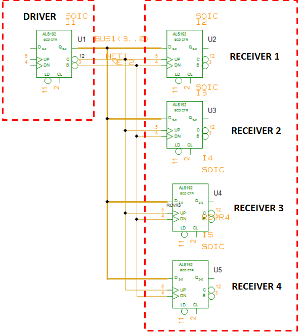
In this example, when an ECSet is applied to NET2 in Constraint Manager, the mapping process can distinguish between U2, U3, U4, and U5 only by Refdes information.
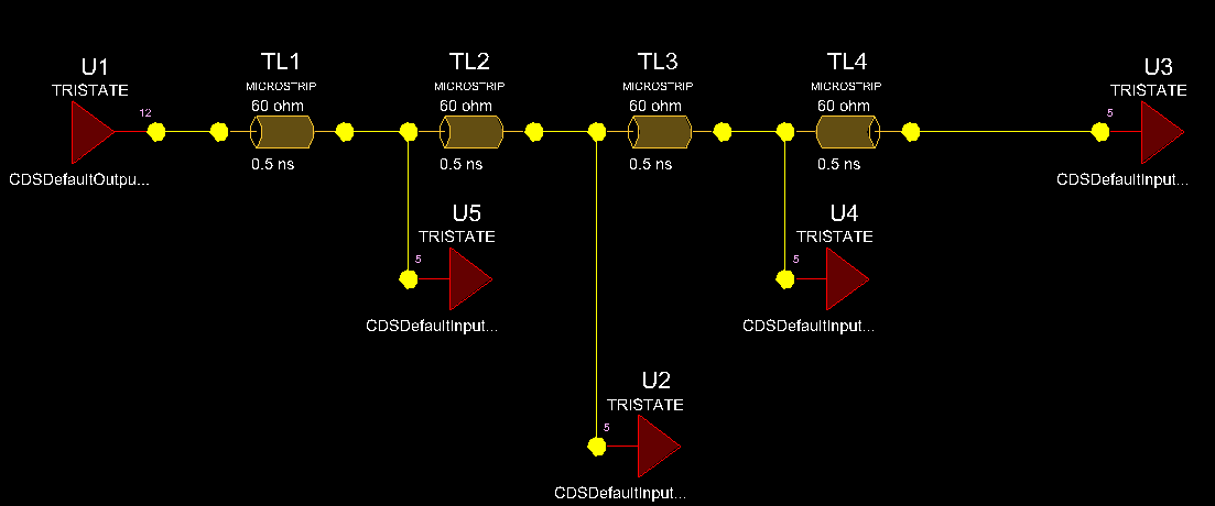
Mapping ECSets to Xnets using Tags
To resolve ambiguities during ECSet mapping, a tag is associated with an ECSet to uniquely identify a pin. Tags need to be defined for all pins that have the same signal model and pinuse. When you apply a tag-based ECSet to an Xnet, these tags are mapped to the corresponding tags on the component/pins.
If tags on the component/pins are missing in a design and a tag-based ECSet is referenced, the mapping process indicates that the tags are present on the ECSet nodes, but not on the component/pins of the target net in the design. Auditing the referenced ECSet, assigned to an Xnet, lets you apply the ECSet tags to the desired component/pins in the design.
The tags on the component/pins are saved as ECSET_MAPPING_TAG property in the design.
The tag-based ECSet mapping solution is available only with the High Speed option.
Mapping ECSets to Xnets in Constraint Manager
If a tag-based ECSet is referenced, but the tags are not used to map the Xnet pins, the applied ECSet appears as an Out of date value (Orange color).

Running the Audit Electrical CSet command on a single Xnet, launches an interactive dialog box to view the current mapping information.
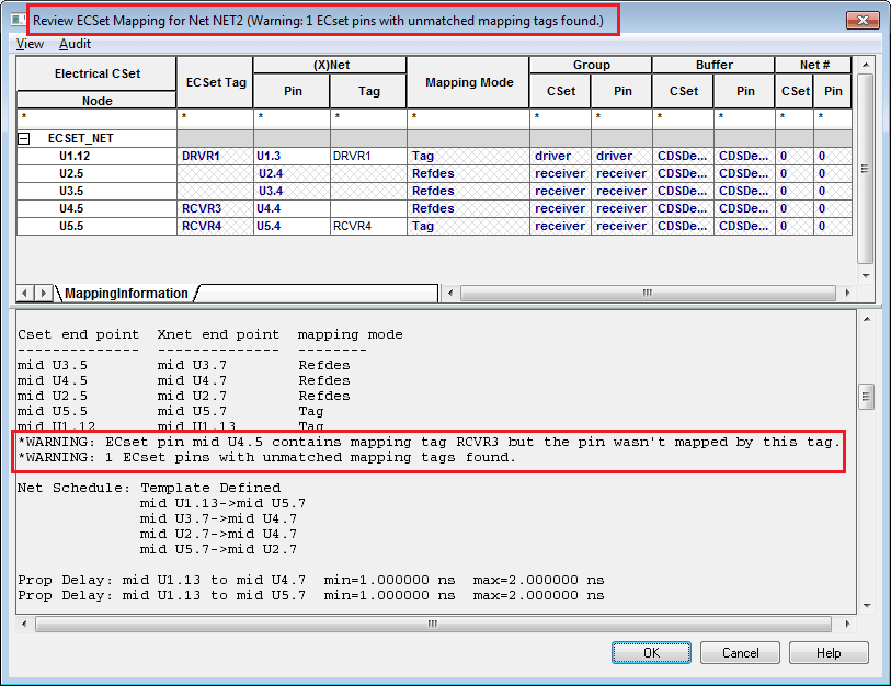
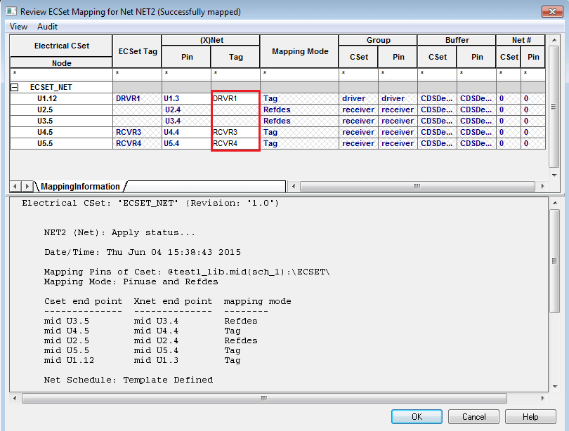
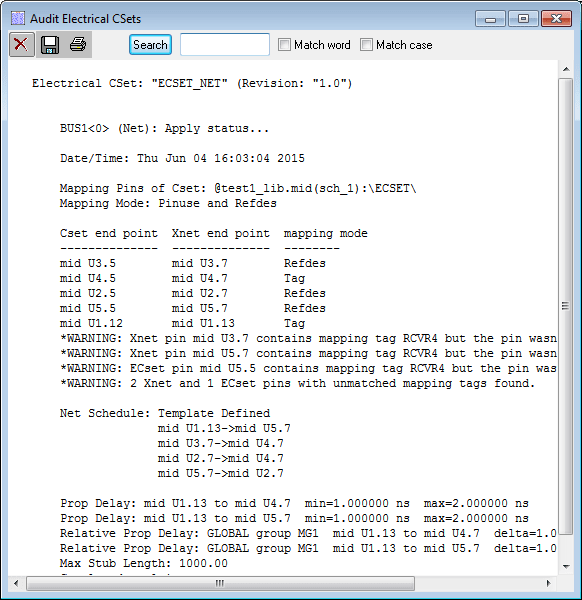
In the Review ECSet Mapping for <net_name> dialog box, you can review the mapping between ECSet nodes and pins of an Xnet. If the tags are mismatched, warnings are reported in the apply log. You can assign the tags in the ECSet to the appropriate pins of the Xnet.

For this example, the pins U1.3 and U5.4 of NET2 are successfully mapped to the ECSet nodes U1.12 and U5.5, respectively.
You can edit the mapped Xnet pins for the ECSet nodes that are tagged using one of the following ways:
- Clear the currently mapped Xnet pins and then select the correct Xnet pin for each ECSet node.
- Edit the tag for the Xnet pin such that re-applying the ECSet maps the Xnet pin to the ECSet node with the same tag.
The tags on the pins of an Xnet are displayed in one of the three forms:
- Read-only (cross-hatched): When the tag is not defined for an ECSet node and there is no pin mapping. For example, the pins U2.4 and U3.4.
- Flattened (thin black): When the ECSet tag is applied to the Xnet pin or the pin mapping is system-generated.
- Directly set (bold blue): When the tag on an Xnet pin is explicitly set in the design or in the Pin tag column, or if pin mapping is user-generated.
After the mapping between ECSet nodes and Xnet pins is done, run the Audit command to apply the mapping. You can apply the mapping in two ways:
- Apply tags to current object: Applies the ECSet to the current Xnet. The ECSet tags are applied to those pins, which do not have tags. In the following figure, the RCVR3 tag is mapped to pin U4.4 of NET2:
- Apply tags to all objects: Applies the ECSet to all the net objects, within the current object’s group, which reference the same ECSet. A warning is displayed to confirm the action.
Constraint Manager applies the ECSet tags to all the Xnets which reference this ECSet. In the following figure, the ECSet tags are applied to BUS1 that uses similar topology/schedule/components as NET2: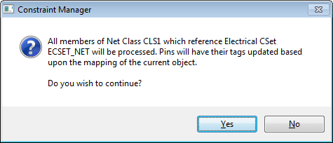

It is recommended that you first Apply tags to current object to confirm the tag mapping for a single Xnet and then use Apply tags to all objects.
If an ECSet is referenced by multiple objects including individual Xnets and group objects, the Apply tags to all objects command is only applied to the members of the selected object’s group which reference the same ECSet.
For this example, NET2 is a member of BUS1 and CLS1. On running the Apply tags to all objects command, all members of net class CLS1 are processed as this group refrences an ECSet. Similarly, if BUS1 references an ECSet, only its members are processed.
If the mapping between ECSet tags and Xnet pins is unsuccessful, the Audit Electrical CSets report dialog box is displayed.
Defining Tags
The tags on the components or pin instances are defined in the database (schematic or layout). The tags on an ECSet are defined in SigXplorer. Tags can be defined in a design prior to ECSet extraction or in SigXplorer when an Xnet is extracted.
Defining Tags on a Component/Pin in the Design
Add tags to a component or pins in a design prior to extracting a topology into SigXplorer. Tags can be set directly in the database (schematic or layout) by adding a property ECSET_MAPPING_TAG on the component or pins.
- In DE-HDL: You can add/edit the tag to the component or pin instance when Constraint Manager is closed.
- In PCB Editor: You can add/edit the tag using the property edit command or in the Pin Properties worksheet of Constraint Manager.
These tags are used when an Xnet is extracted to SigXplorer and when ECSet is applied to that Xnet.
Defining Tags on an ECSet in the SigXplorer
The package pin parameter, mappingTags, is used in the SigXplorer topology file to uniquely identify a pin and remove any ambiguity in the application of ECSets.
Topology Templates Audit
The Topology Templates audit (Audit – Topology Templates) migrates obsolete properties to ECSet references used by Constraint Manager.
The topology templates audit removes the TOPOLOGY_TEMPLATE, TOPOLOGY_TEMPLATE_REVISION, and ASSIGN_TOPOLOGY references from net-related objects.
The Audit Topology Templates dialog box contains the following fields:
| Use this field | To |
|---|---|
|
Topology template values |
List all TOPOLOGY_TEMPLATE and ASSIGN_TOPOLOGY property values in the design. After a property value is selected from the list, all nets which have the same template value are listed. |
|
Update to use Electrical Cset |
|
|
Import (radio button) |
Import a new template. The field beside the radio button is populated with a Topology Template (.top file) name if one exists on disk. |
|
Existing (radio button) |
Use an existing ECSet. This option will be the default if the design contains an ECSet with the same name as the property value |
|
Overwrite existing constraints (check box) |
Controls whether constraint values in the ECSet overwrite any existing net-related constraints when an ECSet is re-applied. |
|
Apply |
Migrates all the listed nets to reference the imported or existing ECSet. After migration, the TOPOLOGY_TEMPLATE and ASSIGN_TOPOLOGY properties are deleted from the nets. |
View the next document: 03 - Inter Layer Spacing Checks
If you have any questions or comments about the OrCAD X platform, click on the link below.
Contact Us