Cables and Connectors: A Bridge to the World Beyond the PCB
We’re a connected society. In a lateral sense, there are connectors of some kind involved in bringing this story to you. The voltage coming out of the wall outlet is often our first introduction to invisible dangers. Most of the time, the wall socket is energized with 220 volts of alternating current. That qualifies as deadly!
The Mains Power, Where it All Starts
Type A and B sockets (110VAC) are familiar in North America along with a few outliers such as Japan. The National Electrical Manufacturers Association (NEMA) is setting local standards for the United States and others that wish to go along with those standards. If you were to say you wanted a NEMA cable, you would get the typical three-prong setup we see shipped with most of our electronic goods.
The other goods get an in-line power supply in the form of a wall-wart that transforms the alternating current to direct current while stepping the voltage level down to a device-friendly level. The beauty of these power modules is that the potential heat and switching noise of the regulator is kept away from the rest of the electronics. Meanwhile, you’d probably end up with USB, wireless or another form of connectivity on the device’s data side.
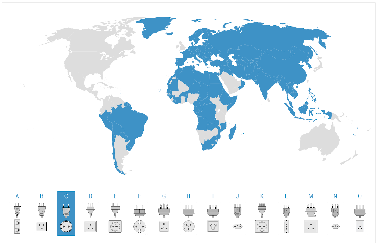
Figure 1. Image Credit: EIC - Shaded in Blue, places where the C style plug and socket are in common use. The A and B plugs/sockets are familiar in the USA and a few other countries.
Some of the “standards” only apply to a single country. You’d be excused for not knowing what type of adapter to bring. The International Electrotechnical Commission (EIC) is the standards body in charge of plugging things in. They have this collection of non-interchangeable connections by design.
The voltage and the cycles per second have to be correct for the electronic device to perform. There is a rule of thumb that says 110-127VAC will swing through its period 60 times per second (60 Hz) and 220-240VAC will cycle 50 times (50 Hz). There are exceptions for both of those general rules. The various sockets and plugs are designed to prevent damage to the device and/or danger to the users. This is relevant in Japan where both 50 and 60 Hz will be used depending on the region.
What about the other end of the cable? Naturally, it has to be something different from the wall side. Document number EIC-60320 covers the gamut of so-called couplers that pair up the other end of the EIC cable with the enclosure. Most of these terminate with lugs to connect to a wire harness but some can be soldered directly to the PCB.
They are rated and advertised for their volt/amp capacity but also for qualification in harsh environments. The conductors used in these cables range from 18 gauge up to 12 gauge stranded wire. Beyond the consumer electronics grade, the automotive and aerospace industries beef up the connectors with locking mechanisms. They will be built to withstand extreme temperatures and acidic or alkaline atmospheres or whatever we can throw at them.

Figure 2. Image Credit Vetco Electronics - Mains voltage will go through a power conditioning circuit after passing through the AC cable.
Once you’ve sorted out what the product is going to do and where it is going to do it, the real fun begins. A multi-board system will rely on a wiring harness and/or stacking connectors that allow all of the features to work as one. From here, the connector options mushroom with choices. Once we’re beyond the cord from the wall to the equipment, there is no standard; not even a splintered regional one.
Connectors Can Be Anything You Want Them to Be
What we have is a handful of connector vendors each with several proprietary lines from each player in this vertical. The choices are amazing. Wherever there is a data transport protocol, say PCIe or Ethernet for instance, there will be an ecosystem of solutions.
You might want a connector with four big pins for power and ground that will also host sixteen little pins for signals. You can look for something like that if you’re good at using the search engine of your favorite component distributor. The 4+16 arrangement was just a random but likely combination of pins. It didn’t take me long at all to find a 4 x 17 giving that one extra wire. Search for a 20-pin connector and scroll down to the more exotic flavors.
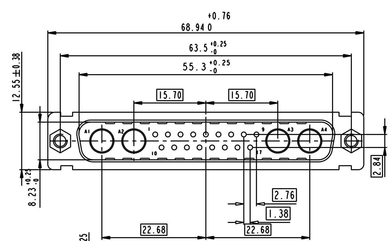
Figure 3. Image Credit: Octopart - Large and small pins can be combined in one connector as required.
This isn’t even a semi-custom solution. The myriad of off-the-shelf possibilities reflect the diversity of applications for connectors. It is a competitive market so one of the differentiators besides price is the ability of the vendor to quickly spin off variants of a family of connectors. For a large enough order, the connector vendors can deliver bespoke solutions where you can name the configuration.
So, not only are there thousands and thousands of connectors right out of the catalog, you can have something done just for you if you’re a good customer. Any one of the suppliers will be happy to keep you well connected. Custom designs will have a longer lead time and some additional Non-Recurring Engineering (NRE) charges for the development. At that point, your special connector becomes another option in the catalog with typical piece-pricing.

Image 4. Image Credit: Author - Imagine this bring-up board with over two dozen mating connectors attached. Always be aware of the airspace required for cables and connecting/disconnecting them.
From simple AC wall plugs to the most intense back panels, the humble connector keeps our electricity flowing from one item to another. They can be a source of noise because of the impedance discontinuity at the pin pad and the proximity to the outside world. This can be mitigated with shrouds and a good ground ring around the entire PCB.
A Final Tip on Creating Footprints for Connectors
Spend the time to get the footprint correct according to the manufacturer. Then make sure the connector vendor didn’t specify something that the fab shop cannot produce. One of the key sticking points can be the hole tolerances when they are too tight. Another likely culprit is when the footprint has metal too close to the PCB edge. Try to resolve these differences by bringing both parties into a conference call.