Power Supply Layout Best Practices
Power supplies are among the most common circuits used in modern electronics. Where there’s a chip, there’s almost always a power supply. Quite often, you will employ a primary power source that is further splintered as required by the parts mix. Additional power domains are created across the board for accessory functions that run on the same voltage or lower voltages. Power delivery takes on many forms, including those made up completely from passive components. Voltage dividers and LC filters are all that’s required in some cases.
Mains Supply Brings Power To And Throughout The Building
Other power domains require a large transformer and all of the trappings of a dedicated power supply. It all starts at a source which, in most cases, is the power grid. Many components make up the grid. A surprising number of the pieces at a power station have a miniature version for use on a printed circuit board assembly. Coils, switches, transformers, fuses and various items bring us safe reliable power which we rely on.

Figure 1. A city’s power supply is essential to making it livable. Printed Circuit Board Assemblies are like a tiny city in that respect. Image Credit: Author
The use of alternating current allows for longer power lines while we usually want to use direct current for PCBA applications. Converting the AC to DC is normally done with a module, either a wall-wart or through a caged circuit where the power cord enters the enclosure. It starts with a transformer to step down the voltage. From there a rectifier takes over to flip the negative dips into positive bumps. Then a big capacitor steps in to smooth out all of the positively charged bumps into a more or less continuous feed of direct current.
The V-out of a power supply will depend on the V-in and the nature of the windings in the transformer. The voltages required will depend on the chip set. Everything used to run on 5V but those days are gone. We typically use 3.3V for normal circuits. Low power circuits may use 2.5V, 1.8V, 1.2V or even lower voltages for some applications. The voltages are just the start of the subdivisions. So, baseline power to a PCB might be +3.3V and regulators would get you the other voltage domains along with the walled gardens receiving their own 3V3 supply.
Linear Power Supplies Are Preferred For Low Noise Applications
Stationary equipment may run off of power from the wall socket, the same as your home electronics. When that level of reliability is not enough, the system relies on back-up batteries that are designed to kick on in an electronic heartbeat. Known as uninterruptible power supplies (UPS), the backup batteries/generators provide continuous service though there may be a voltage spike during the handover.
There are different types of linear power supplies. In my experience, analog electronics tend towards using low drop out (LDO) regulators. Input voltage has to be higher than the desired output voltage on linear regulators. (Another term for “drop out” is headroom.) The LDO allows the input and output voltages to be nearer to one another, typically within a few hundred millivolts. It may require as much as two volts of headroom to operate a standard linear voltage regulator.
Going Mobile Is Going To Require A Battery In Most Cases
Mobile equipment will often run on batteries although there are means of scavenging power from a host device. Security badges and RFID scanners fit this profile. The rest of the time, there has to be a means of charging one or more batteries. The MCP73831 device in figures 2 and 3 is one of many such solutions.
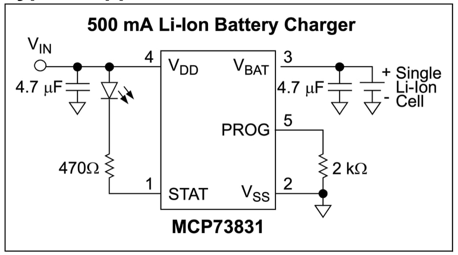
Figure 2. There is more than meets the eye behind this simple circuit. Joining all of the Vss pins to a single point of common ground is typical. Not sure I trust the graphics on pin 3. Image Credit: Microchip
This device is programmable for the voltage level and current. It can be set to drop the current down when the battery hits certain levels of charge percentage. There’s also a threshold for starting the charge, it will not initiate if the battery is charged beyond a certain point. Prior to initiating the charge, there is a preconditioning cycle.
These hooks allow for maximizing the battery life balanced with how much power is available on a fully charged battery. The device features thermal and ESD protection for safety. While the MCP73831/2 series is for coin cell batteries, larger battery charging circuits run on the same principles.
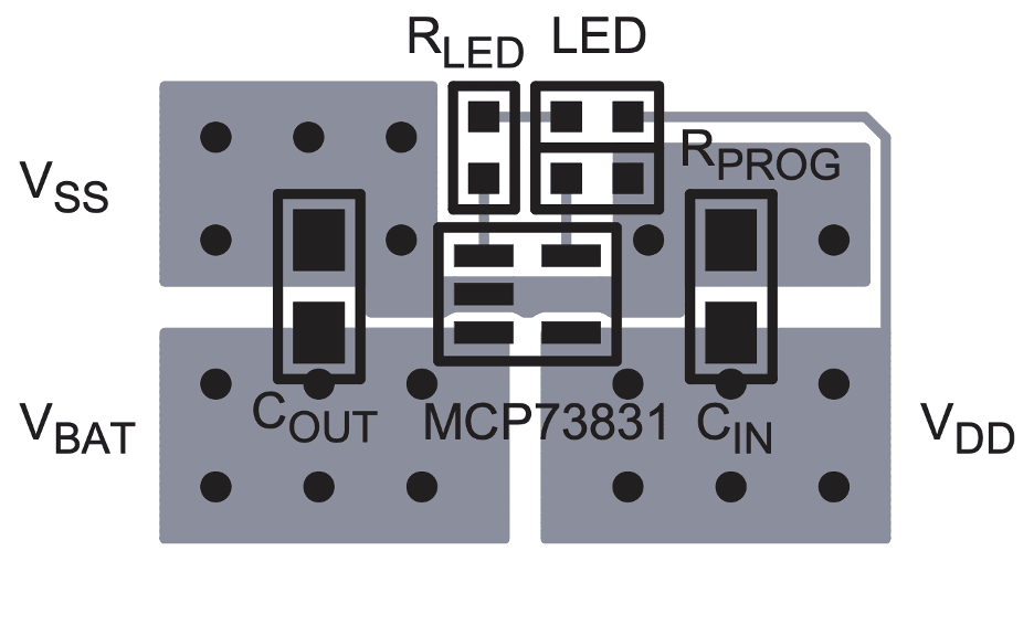
Figure 3. The battery charger’s recommended PCB layout provides what I see as one counterintuitive data point. That would be the thin VDD line that drives the LED. Note that they also have a bottom side view where the VSS (ground) is a rectangle above two others for Vbat and Vdd. Image Credit: Microchip
The Voltage In/Voltage Out process should give us one clear insight to PCB Layout. We want to keep the before and after sections separate from each other. A battery can complicate this a little. We say give and take but a battery has to take first and then give. Power to recharge the battery has to be on par with the expected discharge rate. Many products can be used while they are being charged. If yours is one of those, then Vbat has to be a robust enough connection for those functions to run concurrently.
Switch Mode Power Supplies Can Increase Efficiency By About One Third
Transformers are bulky with considerable weight. They create a measurable amount of heat as wasted energy. Mobile devices cannot tolerate either of these two conditions. The answer comes from switch mode power supplies. There’s no free lunch though. The trade-off is that SMPS devices create a lot of switching noise - as the name would imply.
The typical layout solution includes an inductor that is roughly the same size as the regulator. Some of these packages include an inductor layered above the chip. That can be convenient if you have the head room but lack the board space for the planar circuit. No LC filter is complete without the capacitor which is usually smaller and gets secondary priority to the inductor in terms of placement near the voltage output pin. In any case, a compact layout is the best bet against unwanted noise.
Where possible, I like to create a rectangular layout of the SMPS circuit and then draw a fat line of ground around it like a picture frame. If worse comes to worse the extra space of that box around the circuit can be used to install a little shield can over the noisy device. On a good day, the frame prevents other components from getting too close to the noise source. We always want those regulators to be placed near the pins that use the power.
Power Management Integrated Circuit (PMIC) Helps Consolidate The PDN
High technology equipment often relies on devices that integrate several switch mode power supplies under the hood. One characteristic of the layout is that there are a bunch of LC filters around the device. It always seems like a compromise as the placement gets fleshed out with all of the passive devices crowded together.
Now, picture this if you will; each transistor in a chip represents a person in a city. The citizens will stand by ready to “flip the bit” when given a little jolt of electricity. For example, the Snapdragon 835 chip was on a 10 nm process and had three billion resident transistors to flip. (Fun fact: I designed that one into the Pixel 3 phone and the Daydream VR headset.) To put that into perspective, Tokyo, once the world’s most populous city, has been surpassed by Jakarta, Indonesia, which now claims 42 million residents. Compare that to the new Snapdragon X Elite sporting over 31 billion transistors.
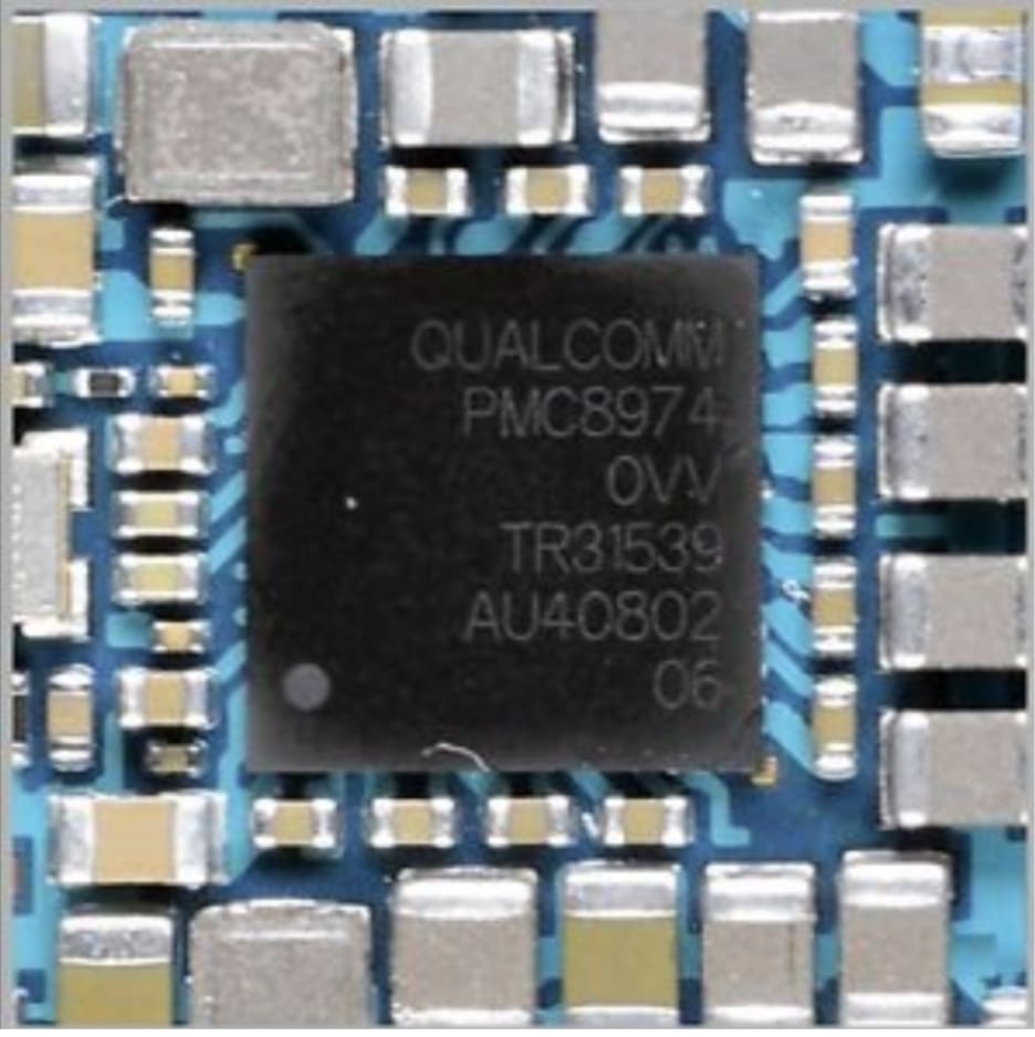
Figure 4. This PMC8974 device from Qualcomm is surrounded by filter circuits for power domains ranging between 2.5V and 5.25V. Newer devices may output a range of half of those voltage values. Features include voltage regulation, DC-DC conversion, and battery management. Image Credit: eBay
The premise behind the PMIC is that there will be a multi-core processor that has numerous voltage requirements. I’ve used as many as three PMIC devices for one highly integrated circuit. Placement is crucial. Items like cameras and other circuits, including an audio CODEC or an accelerometer, will want an isolated power supply of their own. In this manner, it is common to have a PMIC and a number of stand-alone regulators scattered around the printed circuit board.
Fierce competition among companies in a market segment will demand the longest battery life and the smallest form factor. Batteries take up more room in the enclosure with each generation. Meanwhile, performance metrics are the yardstick against which they compete.
Factors such as screen resolution, WiFi speed and range, or other relevant metrics will ultimately determine the winner. Of course, time-to-market is another driver of success. A well-designed power distribution network will be a key factor in who comes out ahead. You have the power, use it wisely by managing the heat and/or noise produced within your project’s grid. It’s pretty rare to get a second chance after the product fails. There are potentially billions of reasons to make your first chance count.