PCB Data Management With OrCAD X
Key Takeaways
- OrCAD X Capture workspaces allow administrators to set team member privileges to protect file integrity.
- Design Review and Markup keep team collaboration focused on project files with internal comments.
- Live DOC ensures project documentation and board design are constantly synchronized.

PCB data management is straightforward and powerful with the OrCAD X File Manager.
Managing files is more important than ever as PCB projects grow in design complexity. The layout must coordinate design intent communicated through engineering documents alongside manufacturer constraints for a PCB production that optimizes performance while minimizing the defect occurrence. The integrity of design files institutes a seamless manufacturing process where the fewest revisions are necessary, tamping down on unexpected expenses or adjustments during hectic production schedules. PCB data management ensures that revision histories are clear and supporting file associations like schematic symbols and footprints are quickly located and easily accessible to team members. With OrCAD X Capture and workspaces, design teams can spend less time on the minutiae of library management and keep team members connected – even remotely – with defined roles and controlled editing/publishing functionality that protects file integrity.
Workspaces Simplify PCB Data Management
In OrCAD X Capture, data management begins with workspaces for collaborative, cloud-enabled design workflows. Privilege settings are customizable for each workspace and allow for various levels of file interaction.
Workspace Privileges by User Type
|
View files |
Edit design files |
Edit library files |
Assign member privileges |
|
|
Users |
✓ |
|||
|
Designers |
✓ |
✓ |
||
|
Librarians |
✓ |
✓ |
||
|
Admins |
✓ |
✓ |
✓ |
✓ |
File Management
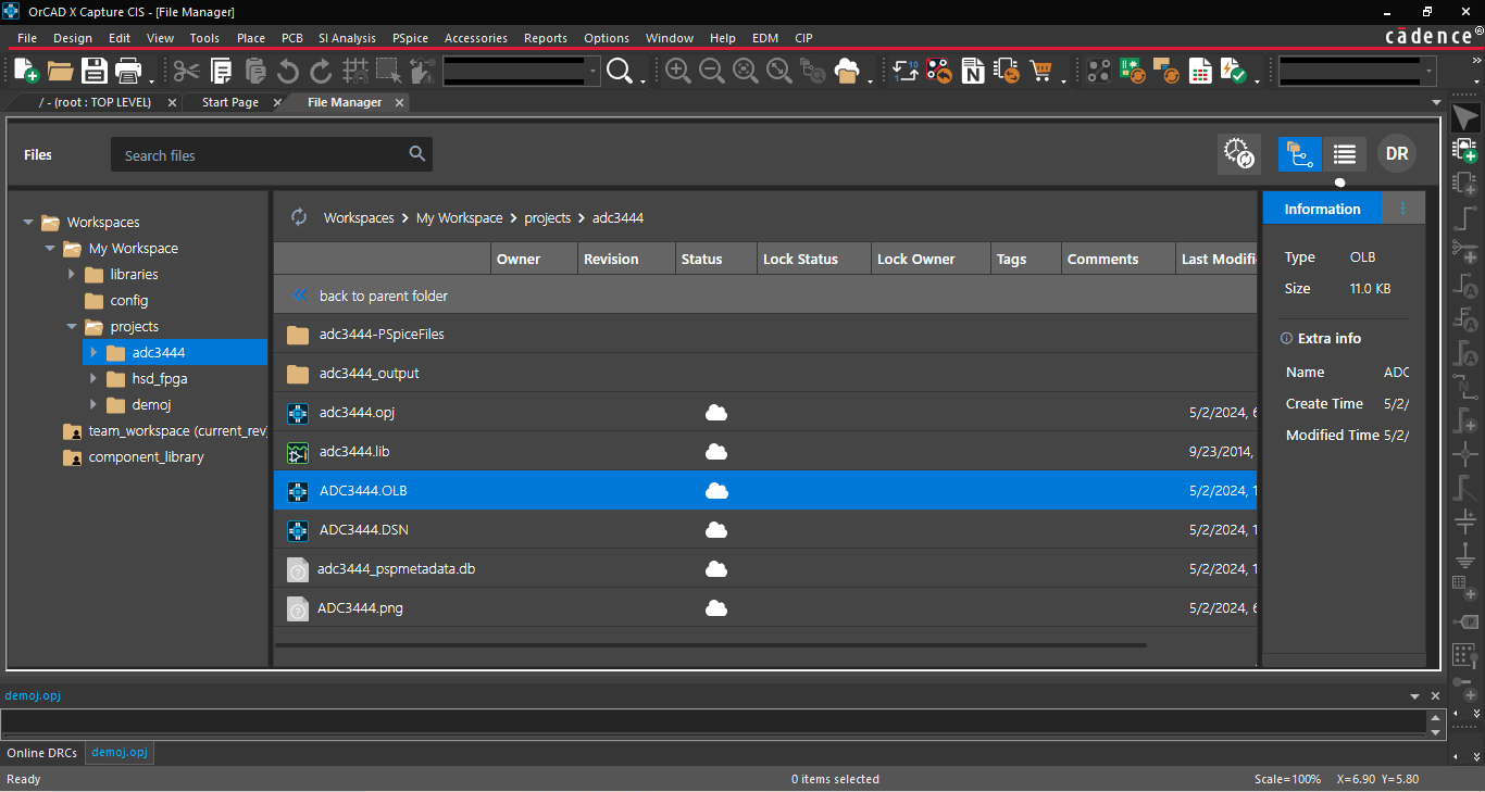
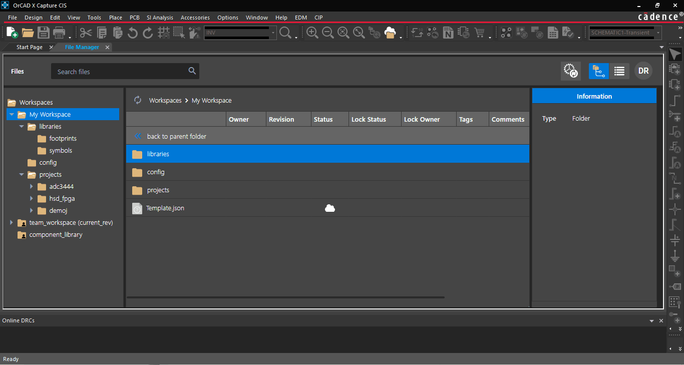
Data management through workspaces begins by saving files to the local workspace directory “My Workspace,” which acts as a central file repository. By default, new files enter the cloud, and designers can then publish files in a shared workspace.

File Manager tab shows the My Workspace folder on the left side.
Recording a version history is also essential for a design rollback to an earlier instance. By adding local projects to a shared workspace, all appropriate team members can access the same version history for a communal progress report of the design files. Cloud integration supports further team integration and task delegation.
Library Management
Starting from the schematic, PCBs incorporate design files representing accurate manufacturing information from component manufacturers. Since many components have standard footprints according to their packaging, reuse of these footprints is essential as a time-saving measure and to enshrine known good files post-verification that reduce manufacturing defects. There are three approaches to footprint creation, and designers or librarians can combine the three methods where appropriate to maximize efficiency:
- Designers can create parts manually. Although this method takes more time upfront, manual footprint creation may be the only option for irregular package shapes, pinouts, etc. So long as package measurements are obtainable, designers will always be able to design manual footprints. The improved part authoring within OrCAD X Presto PCB makes it easy to design footprints for complex and unique components.
- A footprint wizard tool for common packages can quickly produce an accurate footprint with minimal package information due to standardization.
- Leading vendors like SamacSys, SnapEDA, and Ultra Librarian provide libraries of component footprints numbering in the millions that eliminate time spent on large or complex BOMs and errors stemming from footprint creation.
Design Review and Markup
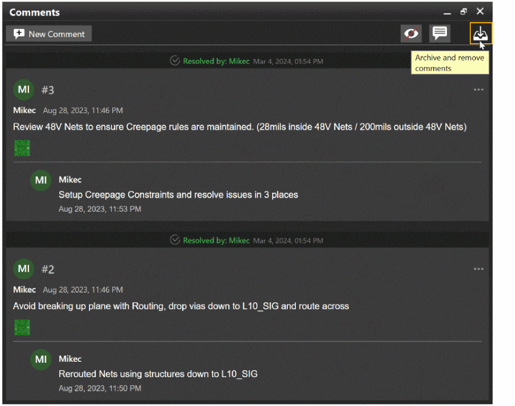
For further collaboration, team members can use the Design Review and Markup feature to comment directly on design files and optimize workflows with communication at the point of interest. Saved comment files are in the local directory; they are not included in file documentation output, allowing teams to communicate at the design level with complete confidence that project discussions remain internal to the team for sensitive matters regarding IP. Designers can archive these comments to enhance organizational record-keeping and even import archived comments into new projects where relevant.

Design Review and Markup comments allow design teams to communicate internally within the project files.
How Live DOC Aids DFM Communication
File management extends to the relayed manufacturing information, and design teams can leverage Live DOC to synchronize documentation with the layout in OrCAD X Presto PCB Editor automatically. Consider an all too common feeling: after preparing documentation files for manufacturing review, a designer realizes that the generated documentation does not represent the most recent changes to the board, perhaps even something as simple as forgetting to include the PCBA part number on the silkscreen layer. Designers have to reproduce manufacturing files, which, while not a particularly time-consuming process, invites the opportunity for a much more grave error: sending out-of-date production files to the manufacturer that can result in a lot of scrappage.
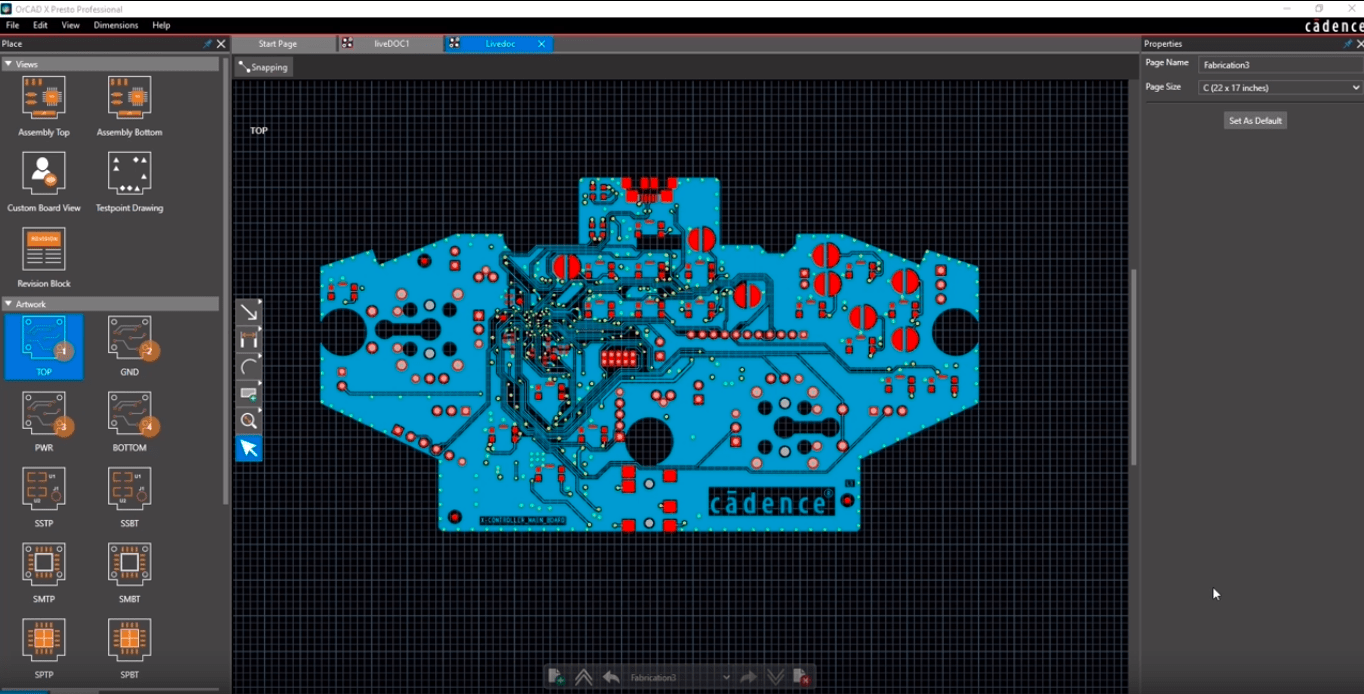
With Live DOC, it’s easy to get ahead of manufacturing documentation issues with a collaborative parallelization that meets modern demands for a left shift in design. Instead of having to wait for file output, designers can actively view the board throughout the layout without interrupting the design workflow. Manufacturers integrated into the design workflow can also catch reworkable board features earlier, saving time on both ends of the production.

Live DOC shows the template overlays on the left and the top layer artwork centered within the canvas.
Since Live DOC is always up-to-date with the most recent design changes (any changes that trigger an automatic save event in the board file also propagate to the documentation generated), designers can rest easy knowing that what they see is what the manufacturer gets. In addition, default and customizable manufacturing templates make it easy to set and adjust file outputs as needed, including support for ISO and AMSE standard page sizes.
Cadence Data Solutions For Any Size of Design Team
PCB data management is an essential consideration for the integrity of DFM boards and is a cornerstone of successful organizations. Proper data management protects libraries by limiting access to trusted team members with administrator-defined roles that prevent accidental file modification. With Cadence’s PCB Design and Analysis Software, organizations can maximize data management/version control and team management at all stages of board development with comprehensive modeling for MCAD-ECAD integration. Interested in learning more? See how the new OrCAD X platform simplifies ECAD workloads with a focus on the user interface.
Leading electronics providers rely on Cadence products to optimize power, space, and energy needs for a wide variety of market applications. To learn more about our innovative solutions, talk to our team of experts or subscribe to our YouTube channel.