Applying IPC PCB Design Standards
Key Takeaways
-
Learn why it’s important to comply with IPC standards for PCB layout design.
-
Find out which IPC standards are relevant to PCB layout design.
-
Learn how the choice of PCB software affects IPC standard implementation.

PCB designs that are compliant with IPC standards are generally more reliable
It’s tedious to read through pages of IPC standards, however, they are there for good reasons, particularly for PCB layout designs. The IPC was established in 1957 and at the time was known as the Institute of Printed Circuit. Today, thousands of companies that are part of the PCB design supply chain are members. When designing for PCB design standards, IPC standards are one of the basic go-tos to help you achieve a successful design.
|
IPC Standard |
Description |
Key Aspects |
|
IPC-2221 |
Generic standard covering nearly every aspect of PCB design. |
- Electrical considerations: PDN bus layouts, conductor clearance, impedance control. |
|
IPC-2222 |
Detailed standard for rigid organic printed board design. |
- Material selection. |
|
IPC-2223 |
Standard specifically for flex PCB designs. |
- Pad/via placement. |
|
IPC-6012 |
Qualification and performance for rigid PCBs. |
- Electrical, thermal, and physical performance requirements. |
|
IPC-A-600 |
Visual inspection standard for PCB acceptability. |
- Conductor spacing and surface finishes. |
|
IPC-7351 |
Standard for surface mount design and land pattern libraries. |
- Component placement and land pattern creation. |
|
IPC-4101 |
Standard for base materials used in rigid and multilayer PCBs. |
- Specifies mechanical, electrical, and thermal properties for PCB materials. |
|
IPC-2615 |
Dimensions and tolerances for printed boards. |
- Specifies tolerance for PCB dimensions, holes, pads, and component placements. |
|
IPC-6013 |
Performance requirements for flexible printed boards. |
- Flex circuit reliability and inspection criteria. |
Why Is It Important to Comply With IPC Standards for PCB Layout Design?
IPC produces and maintains standards that serve as a common guideline for PCB design, fabrication, assembly, test, and other areas of concern. For those looking to adhere to PCB design standards, complying with the relevant IPC standards for PCB layouts can make a difference in a product’s success or failure.
There are just too many variables in PCB design that can affect the reliability and manufacturability of a board. For example, designers could turn to guesswork for the perfect pad size for through-hole components. Designing without the guidance of IPC standards might also lead to non-conformance of uniformity between designers and manufacturers.
![PCB design layout with the IPC-2221 Standard]](https://res.cloudinary.com/uf-552861/image/upload/v1729540594/design-layout_gvu24e.png)
PCB design layout with the IPC-2221 Standard
IPC-2221
Throughout the years, the IPC has established various standards that ensure design reliability and manufacturability. For PCB designers, the must-read IPC standard is the IPC-2221, a generic standard that covers almost every aspect of PCB design.
The standard details how electrical considerations such as PDN bus layouts, conductor clearance, and impedance control should be implemented on a PCB. You’ll also find pages in the standard that focus on thermal design considerations for the PCB. The standard explores various methods of dissipating heat in PCBs and explains how to implement them in actual designs.
PCB design and manufacturing are inseparable sides of the same coin. Some sections of the IPC-2221 help designers ensure the PCB is optimized for PCB manufacturing. For example, section 9 touches on holes and interconnections, which contain guidance on drill size, land pattern, and conductor spacing on a PCB.
IPC-2223
The IPC-2221, however, does not cover guidelines related to flex PCB design. If you’re working on one, you’ll need to refer to the IPC-2223, which exclusively focuses on flex PCB structure design. It covers important design considerations such as pad/via placement, bend radius, coverlays, and structural specifications for flex PCBs.
IPC-2222
Meanwhile, the IPC-2222 standard delves deeper into the requirements for a rigid organic printed board design. This standard details factors that enhance the manufacturability of a rigid PCB, including material selection, hole size, interconnects, and mechanical properties.
Implementing IPC PCB Design Standards With OrCAD X
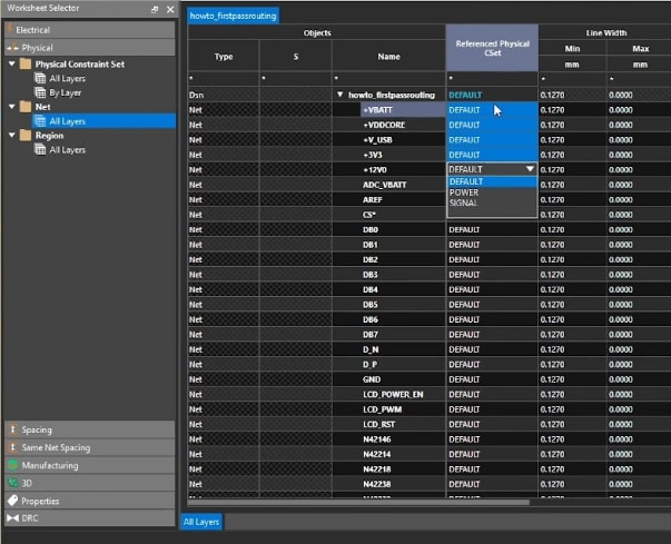
Assigning the physical constraint sets in OrCAD X
Reading the IPC standards isn’t enough to produce PCBs that are both reliable and manufacturable. To do that, you’ll need to implement the standards on PCB software. If you’re using software with limited functionality, you’ll find it difficult to set the required constraints on the software.
For example, the IPC-2221 specifies the recommended component clearance for automatic placement machines. You’ll want to set this value in the software and have it automatically detect violations when the rule is breached.
Component arrangement, thermal management, and other guidelines set by IPC standards are better managed with an advanced PCB design tool. OrCAD X, for instance, offers downloadable component footprints that are compliant with the IPC standards for PCB layout design.
|
IPC Standard |
Description |
Key Aspects |
|
Constraint Manager |
IPC-2221, IPC-2222 |
Enables the setup of physical and spacing constraints like conductor width, trace spacing, and pad size. Helps ensure electrical, thermal, and mechanical reliability. |
|
HDI Routing Support |
IPC-2221, IPC-2226 |
Allows for the use of blind, buried, and micro vias, with easy layer transitions and rule-driven via placement, critical for complex HDI designs with tight space constraints. |
|
Via Arrays |
IPC-2221, IPC-2223 |
Efficiently adds via arrays in various patterns to meet the needs of flex and rigid-flex designs, ensuring reliability and adherence to PCB space constraints. |
|
3DX Engine for Rigid-Flex Designs |
IPC-2223 |
Supports the visualization and manipulation of 3D rigid-flex designs, helping to verify bend radii and reduce errors in flex PCB layouts before manufacturing. |
|
Cross-Section Editor |
IPC-2221, IPC-2223 |
Facilitates the design and editing of layer stack-ups, including the ability to import/export cross-section technology files. Ensures appropriate layer thickness and dielectric properties. |
|
Design for Manufacturing (DFM) Checks |
IPC-6012, IPC-2615, IPC-A-600 |
Provides real-time DFM checks for fabrication and assembly, including package spacing and via placement, ensuring compliance with manufacturing standards. |
|
Design Rule Checks (DRC) |
IPC-2221, IPC-2222 |
Automated real-time checks for rule violations such as trace width, spacing, and signal integrity issues, helping designers adhere to required IPC standards. |
|
Signal Integrity (SI) Analysis |
IPC-2221, IPC-2222 |
Provides impedance and coupling analysis, essential for ensuring trace design meets electrical requirements specified in IPC standards. |
|
MCAD-ECAD Integration with 3D Exports |
IPC-2221, IPC-2223, IPC-6012 |
Ensures proper collaboration between mechanical and electrical teams, verifying board fit within mechanical enclosures and avoiding design errors in rigid-flex layouts. |
Adhering to PCB design standards is important for reliable circuit boards. OrCAD offers advanced features like constraint management for precise spacing and trace width control, HDI routing for compact designs, and real-time DFM checks to catch potential manufacturing issues early. Learn more about how OrCAD and Cadence tools can support your compliance with PCB design standards by visiting the PCB Design and Analysis Software page and OrCAD X.
Leading electronics providers rely on Cadence products to optimize power, space, and energy needs for a wide variety of market applications. To learn more about our innovative solutions, talk to our team of experts or subscribe to our YouTube channel.