Home
Free Trial
Home
Free Trial
Read More
Content
Filter
10 results found
Featured
Allegro X Advanced Package Designer Silicon Layout Option Datasheet
Featured
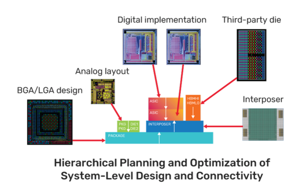
Integrity System Planner Datasheet
Featured
Allegro X Advanced Package Designer SiP Layout Option Datasheet
Featured
Allegro X Advanced Package Designer Datasheet
Featured
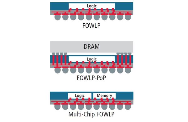
eBook: 3D Packaging vs 3D Integration
Featured
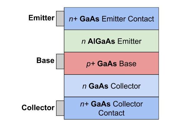
Heterojunction Bipolar Transistors
Featured
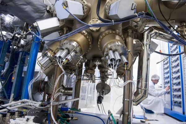
The Molecular-Beam Epitaxy (MBE) Process
Featured
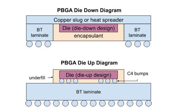
Ball Grid Array Technology Overview
Featured
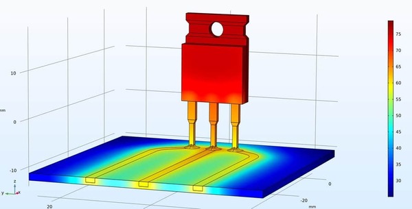
Tips for IC Package Thermal Simulation
Featured
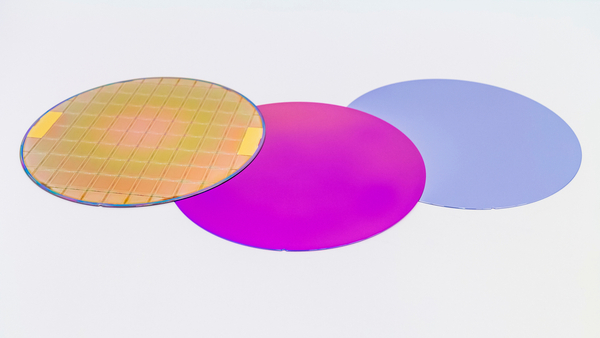
The Different Types of Semiconductor Wafers
Featured
Products
None
Allegro X PCB
(4)
Sigrity X Aurora
(4)
Content types
None
Blog
(9)
Ebook
(1)
Solutions
None
PCB Layout
(3)
Schematic Capture
(1)