The Day a PCB Was Born
I want to take you back to a project that highlights a few twists as all good projects will. 17 years ago I was presented with 20 pounds of potatoes and a 10 pound bag. The bag was shaped like a PEZ dispenser with a crown of gold fingers in place of the plastic head. The actual name of the early form factor was XENPAK. It used the XAUI protocol which has become a popular 10G-for-the-masses deal. My piece of the puzzle sat between the fiber optic backbone and the edge routers that supplied data to medium and large enterprises.
“That inside-out effort lead to an “It’s not you, it’s us” story about how they didn’t need anything from us for a while.”
As an aside, Cisco accounted for about 80% of the merchant market for these transponders. The “merchant market” is the part where the industry is not doing that layer in-house. A small company filing a socket for a huge company is a pretty common scenario. The big guy sneezes, and you get pneumonia for roughly 13 weeks. They liked our stuff and ordered a lot. Then we delivered, possibly beyond their expectations. That inside-out effort lead to an “It’s not you, it’s us” story about how they didn’t need anything from us for a while. Food for thought on how the big manipulate the small. They did award us a technology alignment award for our flagship product – just before canceling our quarter on the 10G part – so we had that going for us, which was nice; sort of.
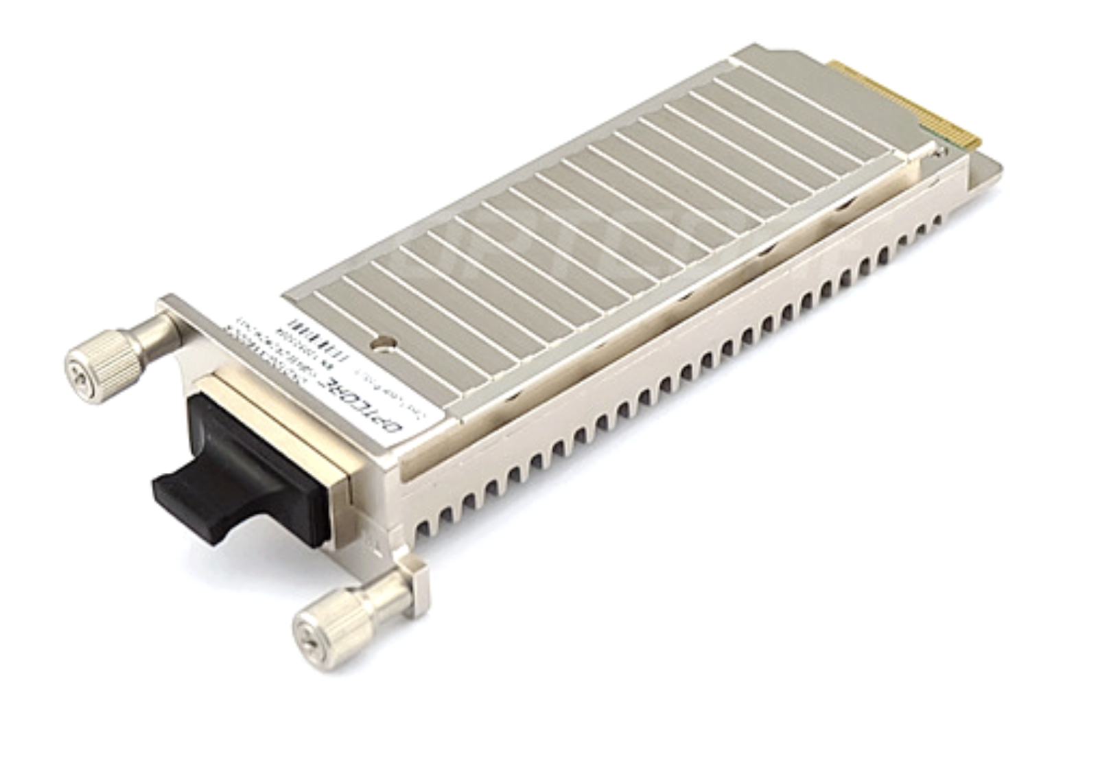
Photo Credit: Opticore - Typical XAUI based 10G device
The Thick (or Thin) of the Plot
Back in that simpler world based in the weeks before 9/11, a good laser and photodetector were some chunky components. The special goodness we were adding was a device that reduced chromatic dispersion, whatever that is, and it allowed us to double the distance between repeater stations along the fiber network. This component was my first exposure to 0.5 mm pitch devices. This pitch, if you didn’t already know, is the threshold where micro-vias become a thing. Mid 2001 was still early-adopter times for HDI, so I definitely had the fab-shop on speed-dial.
These high-performance parts can blink a laser on and off 10,000,000,000 times in a second while reading the blinks from another laser at the same bit rate. When you ask this much of your equipment, it will inevitably end up with an exothermic reaction; toasty IT closets for everyone! We had to check that problem with active cooling. We put a Thermo Electric Cooler (TEC) right between the transmit and receive chains. You will find these TEC devices in the portable coolers that plug into those strange, round, 12V power ports they put in cars. Ok, most of us know them as cigarette lighters. The point is that the “friggin’ laser” and the detector, along with their insatiable appetite for LC filtering, had us over-committed on component placement by about 50%. Call it 7.5 pounds of potatoes and we have to stop short of mashing them together in the PEZ dispenser.
The Squeeze Is On
Connectors were also going through the fine-pitch revolution. We found a stacking connector that gave us a one-millimeter clearance between the top of the lower board and the bottom of the upper board. Not exactly the kind of space PCB dreams are made of. The connector itself needed about ⅓ of the board space on one side of the mother as well as the daughter. If the space of one board is equal to one, the net space after the connectors across two boards comes out to around one and a half.
Feasible, in theory, if you can make good use of the one millimeter between the two boards. It was at this time that I began putting the component height on the layer that defines each footprint’s X and Y extents. This is useful information to have whenever the board’s overhead space is at a premium. A one-millimeter tall inductor would result in zero head-room in that corresponding area on the other board. It wasn’t as though either side could have half of the headroom and pull this off. The contours of one define the limits of the other.
Splitting the Schematic
Breaking up the circuit came down to one characteristic: the 10G path had to come and go on the bottom board. There was no RF, no micro-vias, and no selective gold finish on a regular four-layer FR4 daughtercard. I still recall that the vendor had no DFM issues on the cheap board. My manager at the time had no tolerance for feedback from the fabricator. He read those calls and e-mails as documentation or engineering failures. We typically read them as standard line width and material negotiations. You can thank that nameless but brilliant man for all those times I’ve told you to get your stack-up approved ahead of the routing gate.
Moving Right Along
The newly minted daughter card was only smaller than its parent by the mom’s gold fingers. Removing everything we possibly could and squeezing through an interactive placement of shared headroom was just enough to pull it all together. It was a small company called Big Bear Networks, and I had one PCB Layout contractor on board with me. The layouts would be super dense because we would use the same core circuit for the XENPAK DWDM and a couple other transceiver form-factors. Overlap the three outlines, and only the common area is for component placement. In this way, we could deploy different SKUs using the same basic circuit.
Given such tight confines, I challenged the contractor, and we both tried to complete the placement within the common area. I was still trying to place the last two parts when he completed his version. Nearly all of his shunt elements were facing the edge of the shield with the ground pin out. It lengthened the inductive loops a bit but gave that extra sliver of room. His version also sent a segment of the 10G TX line to an inner layer. Mine was an outer layer solution with all of the shunted elements rotated with their ground pins towards the transmission line. I wanted everything with no compromise. Anyway, full stop. The consultant completed his lower board while I generated the upper board using an imported image of his placement for reference.

Image credit: Finisar - X2 form factor, one of the smaller Multi-Source-Agreement platforms for XAUI.
Winner, Winner, Chicken Dinner!
The boards came in, everything fit and the thermal readings were undernot out of control. The engineering samples had beautiful open eye diagrams, and the big Cisco order followed. You know the rest except the part where I eventually left this operation to flip the bit back to analog and rejoin previous management at a new company with a wider customer base. Then, as now, the valley (and the world) thrives on new ideas. Keep up your skills and keep getting those design wins.