Common Waveform Conversion Circuits
When designing analog circuits, it is often necessary to convert an input waveform into a different output waveform. For example, a sine wave signal may need to be converted into a square wave for digital logic applications. There are also needs for waveform conversion and conditioning, such as when capturing a signal from a sensor. There are a variety of circuit designs that can accomplish these types of waveform conversions.
In this guide, we’ll show some common example circuits that can be used for waveform conversion, specifically for conversion between common types of waveforms. These can be built from active or passive components, most often appearing as various types of filter or amplifier circuits. This can often be much easier than direct synthesis of a waveform with a DAC, and they can be used in all-analog systems without requiring any digital sub-system.
Square Wave to Sine Wave
Converting a square or pulse waveform to a sine wave can be accomplished through simple low-pass filtering or by more complex methods when a purer sine wave is needed. The bandwidth requirements and harmonic content requirements dictate the complexity and performance of the filter. Some of these methods include:
-
RC or RLC low-pass filtering
-
Higher-order brick-wall filters
-
Active filters
The simplest approach is an RC low-pass filter or a critically damped RLC filter. This can smooth the edges of a square wave and remove some harmonics depending on the cutoff frequency, but there will still be some harmonic distortion in the output sine wave, so this approach is generally unsuitable when a pure sine wave is needed.
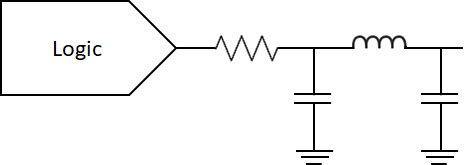
One option for converting a logic-level signal to a sine output while matching impedance is to use a pi filter with a matching resistor. This type of circuit with the series resistor on the output can be appropriate for use in matching to an RF transmission line at 50 Ohms impedance without excessive voltage drop across the resistor. Based on the impedance matching provided by the pi section, the impedance can be transformed from a moderate resistance (such as 68 Ohms or 100 Ohms) into a target of 50 Ohms.
Sine Wave or Arbitrary Wave or Square Wave
Sine waves or arbitrary waves can be used to generate square waves. This is often accomplished using amplifier circuits, which will allow for fast rise and fall times for square wave generation. This can be accomplished from a messy periodic waveform directly, or from a sine wave, depending on whether the resulting duty cycle needs to be perfectly at 50%.
|
|
|
|
|
|
When true sine waves are needed with minimal distortion or leftover harmonic content, active amplifier circuits can be used. For example, a two-transistor differential amplifier circuit provides high gain while avoiding transistor saturation.
Arbitrary Wave to Sine Wave
When the input waveform is irregular, but a stable sine wave output is needed, oscillator circuits can be used to generate the desired output. For example, there are several oscillator types that can be used:
-
A Wien bridge oscillator can lock onto the waveform’s fundamental frequency while filtering out harmonics through its internal feedback network
-
A voltage-controlled oscillator (VCO) circuit can generate a sine waves over a wide frequency range based on an input control voltage
-
Oscillators work very well as adaptable sine wave generators from unstable input signals
Once the sine wave is generated, it can be manipulated into other types of waveforms, such as a square wave.
Square Wave to Triangle Wave
A triangle wave can be generated from a square wave with an integrator circuit operating on a square wave. The integrator requires an input square wave with fast edges and 50% duty cycle to produce a sawtooth wave with minimal distortion. There are two methods that are commonly used:
-
Use an RC charge/discharge network with a very long time constant relative to the input pulse width
-
Use an integrator circuit built from an op-amp, a resistor, and a capacitor
Note that unless tunable varistors or varactors are used in an integrator circuit or RC circuit, the circuit values will only be useful at a specific frequency.
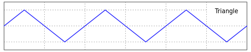
Because this initially starts from a square wave, the process may initially require an arbitrary wave fed into a square wave generator. As long as the integrator receives a square wave at the input, any initial waveform can be used to ultimately generate a triangle wave. The image below shows the resulting triangle wave. There can be some deadtime at the high or low ends of the waveform, which can be seen on an oscilloscope.
Whenever you want to build and analyze your waveform conversion circuits, make sure you simulate your designs with the complete set of tools in PSpice from Cadence. PSpice users can access a powerful SPICE simulator as well as specialty design capabilities like model creation, graphing and analysis tools, and much more.
Subscribe to our newsletter for the latest updates. If you’re looking to learn more about how Cadence has the solution for you, talk to our team of experts.