Seamless Schematic Simulation with OrCAD X and PSpice
Key Takeaways
-
Using schematic simulation reduces costly errors, accelerates time-to-market, and enhances overall design performance.
-
With tools for analog, digital, and mixed-signal simulations, OrCAD X ensures reliability across diverse circuit designs.
-
PSpice test benches allow designers to isolate critical sections of large circuits for focused analysis and optimization.

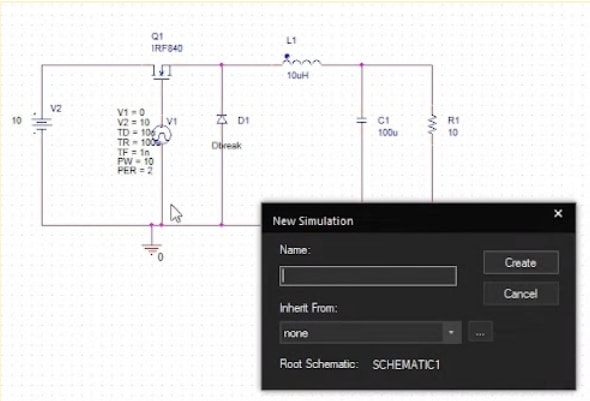
Creating a new simulation in PSpice from a schematic
Schematic simulation bridges the gap between theoretical design and real-world functionality. It allows you to virtually test and validate your circuit designs under various conditions, minimizing errors and revisions in the design process. Without schematic simulation, you might face issues like signal integrity problems, excessive noise, or thermal overload—all of which can lead to product failures.
To make the most of schematic simulation OrCAD X and PSpice step in. OrCAD X, bundled with PSpice simulation software, provides an integrated environment to analyze, optimize, and perfect your circuit designs before moving to production. Let’s explore how OrCAD X makes schematic simulation seamless.
PSpice Bundled with OrCAD X Enables Schematic Simulation
OrCAD X platform is an advanced PCB design software that integrates schematic capture, simulation, and layout into one comprehensive solution. Its PSpice simulation engine, advanced mixed-signal analysis tools, and extensive library of components empower designers to achieve simulation precision. Whether you're working on analog, digital, or mixed-signal designs, OrCAD X offers the tools to innovate and optimize at scale.
Step-by-Step Guide to General Circuit Simulation in PSpice
|
Step |
Details |
|
1. Create a PSpice Design |
- Open OrCAD Capture. |
|
2. Place Components |
- Open the Place menu and navigate to PSpice Component > Diode to add components. |
|
3. Add Voltage Sources and Ground |
- Go to PSpice Components > Modeling Applications. |
|
4. Wire the Circuit |
- Select the Wire icon from the toolbar. |
|
5. Set Up Simulation Profile |
- Navigate to PSpice > New Simulation Profile. |
|
6. Add Markers and Run Simulation |
- Place voltage markers on the schematic at key points (e.g., DC voltage source, load resistor). |
|
7. Analyze Results |
- In the simulation graph, observe the red waveform (output voltage) and green waveform (input voltage). |

PSpice also enables digital logic simulations
PSpice Enables Digital Schematic Simulation
PSpice allows for the simulation of digital circuits, such as counters, to ensure that their logic and behavior meet design requirements before implementation. This section overviews key capabilities and steps to create and simulate an 8-bit counter circuit.
-
Component Placement: Supports digital ICs, pull-ups, pull-downs, and clock sources, enabling accurate modeling of digital logic circuits.
-
Stimulus Configuration: Allows configuring digital stimuli (e.g., clocks) with specific frequency and duty cycle to drive the circuit.
-
Gate-Level Simulation: Enables transient analysis and gate-level state configuration for precise simulation of digital logic behavior.
-
Visualization: Provides trace analysis for viewing the outputs of multiple states, aiding in validation of the circuit's functionality.
OrCAD X Digital Schematic Simulation Steps
|
Step |
Details |
|
Create a New Project |
- Launch OrCAD Capture. |
|
Place Digital Components |
- Add pull-ups and pull-downs using the Place > Component menu. |
|
Configure the Digital Stimulus |
- Right-click the digital clock source and select Edit Stimulus. |
|
Complete the Circuit Design |
- Wire the pull-ups, pull-downs, clock source, and counter ICs. |
|
Set Up Simulation Profile |
- Click Create New Simulation Profile. |
|
Configure Gate-Level Settings |
- In the simulation profile, navigate to Options > Gate-Level Simulation. |
|
Run the Schematic Simulation |
- Select PSpice > Run to perform the simulation. |
|
Add and Analyze Traces |
- Use the Add Trace button to select outputs (e.g., QA, QB, QC, QD) of both counter ICs. |
|
Save the Project |
- Save the project and results for future reference or documentation. |

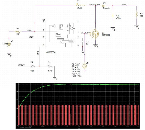
Arbitrary example circuit and associated simulation testbench results in OrCAD X PSpice.
Simulating Sections of Complex Designs with Test Benches
When working on complex schematics, simulating the entire circuit can be time-consuming and resource-intensive. PSpice offers a powerful feature called test benches, which allows designers to focus on critical sections of their schematic for targeted analysis.
This approach streamlines the simulation process, enabling faster validation and optimization of key components without the need to configure the entire design.
-
Test benches in PSpice let you isolate specific parts of a circuit, such as a boost converter or control module, and simulate them independently.
-
By enabling only the relevant components, handling floating nets, and defining targeted simulation profiles, you can efficiently analyze functionality within a controlled environment.
-
This capability saves time and reduces complexity, making it ideal for optimizing subsystems in larger designs.
Why OrCAD X With PSpice is Ideal for Schematic Simulation
OrCAD X with PSpice offers a comprehensive solution for schematic simulation. PSpice simulation engine supports both analog and mixed-signal analysis, allowing users to perform transient, DC sweep, AC sweep, and bias point simulations. Advanced features such as temperature sweeps, sensitivity analysis, and Monte Carlo analysis help refine designs, improve reliability, and reduce costs.
With access to over 33,000 simulation-ready models from leading IC vendors and wizard-based tools for custom component creation, PSpice simplifies even the most complex design tasks. Whether optimizing performance, analyzing trade-offs, or simulating multi-mode designs, OrCAD X with PSpice ensures seamless integration and accurate results. For engineers tackling high-performance and reliable designs, this combination is a trusted choice in the industry.
Schematic simulation is an important step in ensuring your circuit designs are optimized and reliable before manufacturing. Ready to enhance your design workflow? Explore Cadence’s PCB Design and Analysis Software to learn how OrCAD X can revolutionize your approach to schematic simulation. Dive into the possibilities with OrCAD X and achieve unparalleled accuracy in your PCB designs.
Leading electronics providers rely on Cadence products to optimize power, space, and energy needs for a wide variety of market applications. To learn more about our innovative solutions, talk to our team of experts or subscribe to our YouTube channel.