Split Plane Routing in Cadence’s Allegro PCB Editor
Key Takeaways
-
The benefits and concerns of using split planes in a circuit board.
-
PCB design guidelines when working with split planes.
-
The best PCB design tool practices for creating and editing split planes.
The split power planes of a circuit board design
In a perfect world, your car would never run out of gas, ice cream wouldn’t have any calories, and there would always be plenty of room for power and ground on a circuit board. But, since we live in an imperfect world, those are just pipe dreams. While we can leave the car at home and skip dessert, we do still need to make sure that all of the different power and ground nets on a circuit board are fully connected. Doing this in an age where circuitry density continues to grow while board real estate shrinks often means having to use split planes to route power and ground.
Over the years, PCB design CAD tools have grown in their ability to work with power and ground planes. Layout designers now have multiple methods of creating planes on their board, including splitting them. Though, as they say, with great power comes great responsibility, and that is especially true when working with split planes. In this article, we’re going to look at some of the benefits and cautions of split plane routing on a PCB layout, as well as how to use the tools to create what you need.
The Pros and Cons of Split Plane Routing in a PCB Layout
The circuit density on a printed circuit board is much greater than it used to be. Component package sizes are smaller and yet carry more pins, and fabrication methods have improved, allowing for smaller trace width and spacings. All of this has resulted in a lot more circuitry on a board than what there used to be. To add to the complexity, the circuitry on many boards requires multiple power supplies to provide different voltages. In some cases, several different voltages are in use on the same device. This necessitates some intricate routing of power traces, or multiple power plane layers. Here is where split planes are not only beneficial, but essential to the design of the circuit board. By routing the different voltages on one power layer using split plane routing, the power nets on the board will be completely connected without having to add additional layers.
On the down-side, splitting a plane can cause some problems if care isn’t used in a layout. Split planes have the potential to introduce signal integrity problems such as noise and crosstalk into a design. There is also the problem of a split plane interfering with clear signal return paths if the reference plane is what is being divided. Signal returns that don’t have a clear path back to their sources can create a lot of EMI as they wander around the board.
Split planes are obviously important to successfully design a complex PCB with dense circuitry requirements. To avoid the problems that we’ve talked about, let’s look at some of the PCB design guidelines designers should be aware of when working with split planes.
A row of vias in a plane can block off the clear return paths of sensitive trace routing
PCB Design Guidelines When Working with Split Planes
Before you split a plane, you need to plan out what it is that you need to accomplish. To get the best distribution of power for the split plane, you may have to adjust the placement of your components, or rotate them to a more optimum position. Highlighting the power nets that you are working with will prove useful here, as well as color coding them to make them easier to distinguish from each other.
Power planes can be split, but it is best not to split ground planes. This can result in EMI being created and ruining the signal integrity of the board. Split planes are also commonly used for different supply voltages, but not for splitting up power between the analog and digital sections of the board. Remember that these board layers may also serve as reference planes for signal returns, and split planes can pose problems for those return paths. Here are some trace routing reminders associated with split planes:
-
Do not run traces, especially sensitive high-speed traces, across a plane split. The signal return will have to find another way back to the source, which can potentially create EMI.
-
If a ground plane has to be split into analog and digital grounds, only allow a single point of connection between the two to avoid any unintentional loops or antennas being created.
-
Be careful of other obstructions in the planes that can also block signal return paths. This becomes very important for split planes, which sometimes are narrow in design, and a row of tightly spaced vias could easily choke them.
Now that we’ve looked at some of the guidelines for working with split planes, let’s see how the PCB design tools can help in their creation.
Using the copper pour feature in the PCB design tools to create a small area fill
Creating Split Planes in Allegro PCB Editor
There are many different ways to work with planes in the Allegro PCB editor. Let’s take a look at a few of them to demonstrate how a split plane can be created.
Copper Pour
In the picture above, you can see an example of a small area fill being created, which is also known as pouring copper. Although this is a very small area with only two net connections, the principle is the same for creating a larger split plane.
To create a copper pour you will start by adding a polygon shape, which will first open up the options tab for you to configure with the attributes for the plane. These will include specifying the active class as being “etch,” designating the board layer that you want the polygon created on, and selecting the net name for the copper pour to be associated with. Once properly configured, you will then create the polygon by clicking your mouse at the required points on the screen, making sure to encapsulate all of the pins of the power net within the polygon. Once completed, the polygon will become the copper pour, which is an intelligent net object connecting the associated pins together. By creating multiple copper pours on a single layer, you will be able to route your split planes.
Split Plane
The next method is to take a completed plane, or copper pour, and split it. In the picture below, you can see in the upper left corner a simple net between two vias that we want to connect with a split plane. The first step is to draw a line around the area that needs to be split, but in this case we will designate the line as “anti etch” instead of etch as we did with the polygon in the last example.
With the line completed, we will then initiate the split command, as you can see in the upper right corner of the picture. This will bring up additional menus for us to designate the net names of the existing plane and the new split that is being created. Once these parameters have been set up, Allegro will finish the job and create the split plane, as you can see at the bottom of the picture.
Now that the split planes have been created, let’s take a look at ways you can modify them and help yourself with their creation.
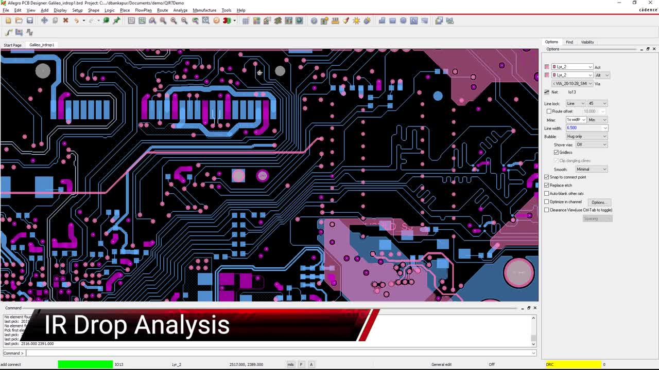
An example of creating a small split plane in the Allegro PCB Editor
Additional Features in Allegro to Help with Split Plane Routing
A copper pour, or split plane, can be modified after its creation in a couple different ways. First of all, by using the shape editing features, you can select the split plane and then drag its edges out to a new position. Another method is to use the edit boundary command to select the shape for alteration. With the shape selected, you can then draw new contours to it, which will be folded into the main shape of the split plane.
We mentioned earlier the advantage to being able to change the color of the nets, which makes it very easy to see where you need to create your split planes. Allegro not only gives you the ability to do this in its color dialog menu, but you can set up different colors for many other design elements as well. These include board layers, silkscreen shapes, reference designators, and much more. You can also assign fill patterns to these elements as well as change the amount that they are shaded so as to make some elements stand out against others.
For additional information on trace routing and creating planes in PCB design, take a look at our E-book.
If you’re looking to learn more about how Cadence has the solution for you, talk to us and our team of experts.