BOM Schematic Design Tools With OrCAD X
Key Takeaways
-
The schematic and BOM form the basis of the netlist that drives the board layout.
-
Changes in the BOM – or entirely distinct variants – will lead to updates in the schematic; OrCAD X helps design teams keep track of these variations.
-
It’s easy to allocate changes between BOM variants using inherited groups and subgroups.
The BOM schematic must contain all the components of the final assembly.
During netlisting, the schematic transfers all logical data from the schematic and all component footprint data from the associated schematic symbols necessary to integrate the components with the bare board assembly. The interplay between the bill of materials (BOM) and the schematic is crucial. A BOM schematic must account for a particular iteration, version, or design revision. Still, the schematic may have multiple variants to account for different production levels (e.g., prototype vs. mass production) or restrictions on component materials.
OrCAD X Tools for BOMs and Schematics
|
Schematic |
BOM |
|
|
Building Out the BOM Schematic
The BOM and schematic combine to build netlist properties and specify the necessary assembly components. These two design documents have an alternating workflow: while the BOM initially derives from the schematic, changes to components arising from market forces (cost, supply, and lead times), differences in assembly integration method, package size/pinout, and other factors mean the BOM isn’t anywhere close to being set until finalizing the schematic.
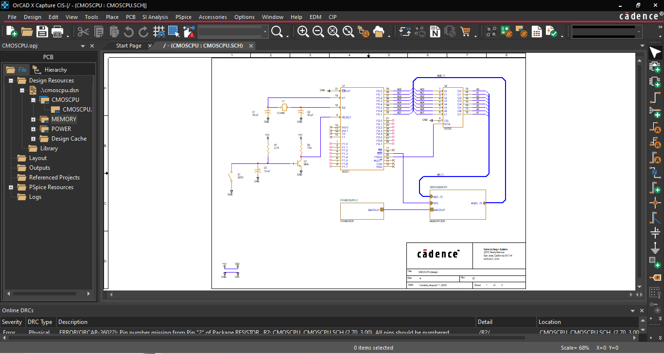
Schematic design usually consists of building out discrete circuit blocks representing some individual functions of the circuit to make the task more manageable (there’s additional work in smoothing/facilitating communication between these circuit blocks); the general scope will focus on adding passive elements for power integrity and active elements for signal conditioning. These ancillary circuits ensure power delivery remains constant and maintain optimal communication between different sub-circuits of the design. The final step for the schematic will be associating the correct footprints to their corresponding schematic symbol, establishing consistency between the symbolic logic and physical pinout.
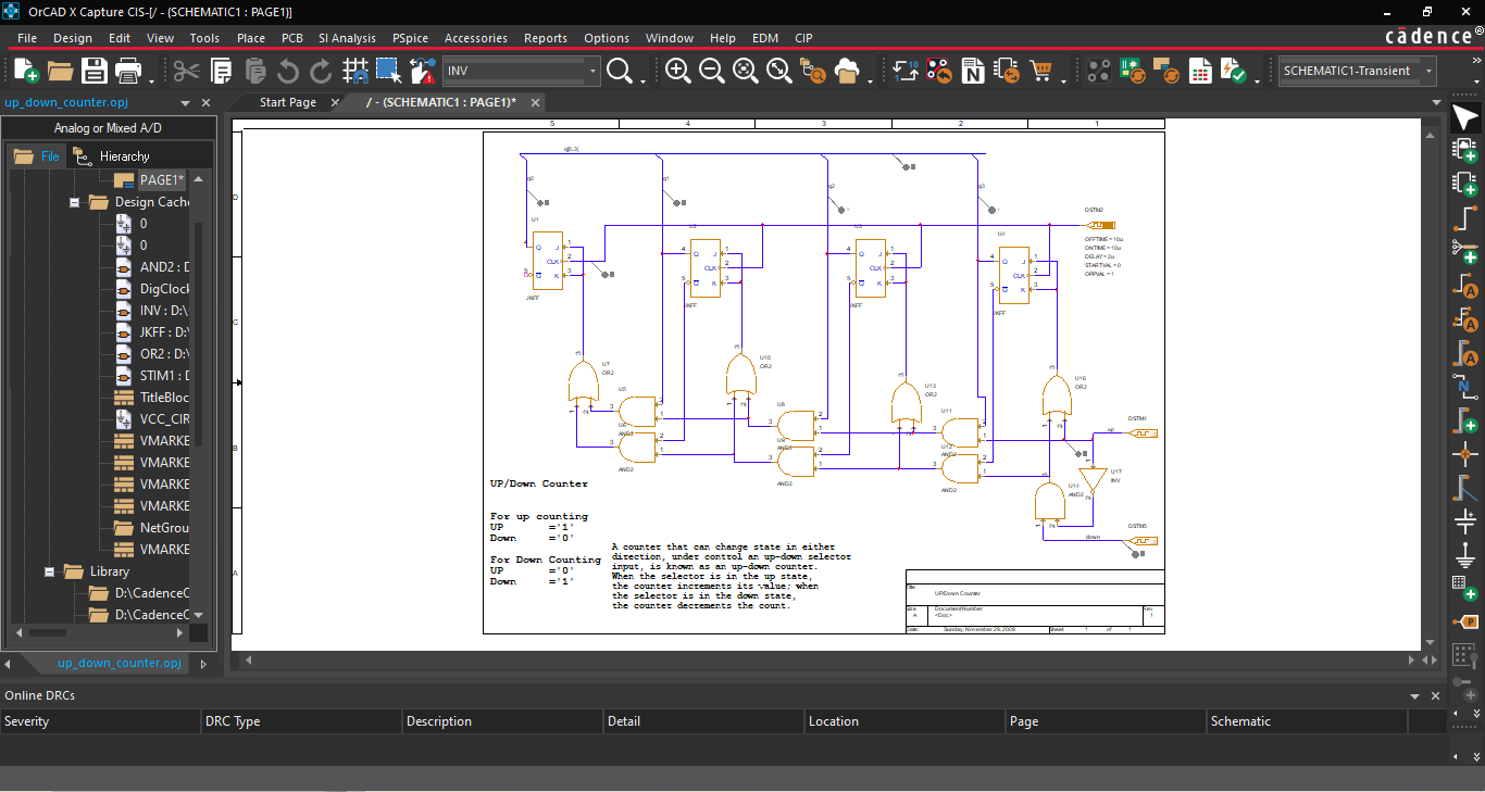
The panel to the left of the schematic workspace shows the file hierarchy and circuit blocks.
Keeping Track of Schematic BOM Variants
During product development, features and scope of the circuit may change due to end-user demands or the general uncertainty of designs as they approach first-pass manufacturing. Design variants relating to “do not install” (DNI) components may necessitate separate BOMs to encompass the component changes and keep track of alternate schematic options. Managing a single BOM is challenging, but ensuring consistency between multiple BOM variants while adding or removing circuit blocks can quickly result in procurement or manufacturing issues if improperly executed.
With OrCAD X Capture, it’s easy for users to build variant BOMs from the core schematic design. Users can define groups and subgroups within the Part Manager to categorize BOM variants for supply chain resilience, differences in regional material requirements, and other manufacturing considerations:
-
Groups represent discrete circuit functionality, such as power and memory. Whenever designers need to add or swap circuit functionality, the group handles all changes to the BOM.
-
Subgroups are group variants that reflect the same or similar functionality with different components, like changes in passive component values, tolerance, package type, and other attributes.
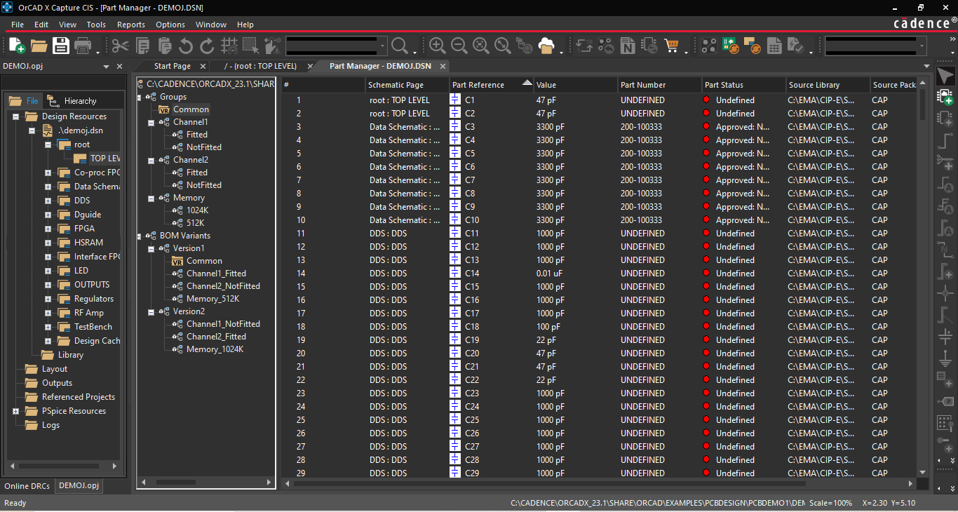
The Part Manager has options for BOM variants of the core schematic design.
The Common folder at the top of the Part Manager tree stores all the unassigned components associated with the design, i.e., all variants of the core design inherit the components within the Common folder. Moving components to groups and subgroups removes them from the Common folder and allows for association with a BOM variant. This structure makes it easy to manage the BOM contents of the core design and variants simultaneously, as designers only exert minimal work defining the differences between variants, expediting design turnarounds. When selecting the Link Database Part command for the CIS Explorer, the core design and BOM variants will update contextually:
-
Linking components from the root folder will update the core design and all groups and subgroups inheriting from Common.
-
Linking components from a group or subgroup folder will only update the component for all particular group or subgroup occurrences. A warning message will be displayed to prevent netlisting and downstream assembly issues if there is a mismatch between the footprint of the core design and the updated component in the group or subgroup.
Cadence ECAD Software Solutions
The BOM schematic interplay is a critical point in developing electronics pre-layout: careful considerations for performance, functionality, cost, package size, and other aspects will determine how effectively the assembly meets the design intent. OrCAD X makes meeting these benchmarks easier than ever with built-in features like Part Manager and Live BOM that make managing multiple BOMs and schematics within a project straightforward and intuitive. Looking to optimize your design even further? See how Cadence’s PCB Design and Analysis Software meets the challenges of modern-day PCB development.
Leading electronics providers rely on Cadence products to optimize power, space, and energy needs for a wide variety of market applications. To learn more about our innovative solutions, talk to our team of experts or subscribe to our YouTube channel.