How Is Impedance Measured With Measurement Circuits?
Key Takeaways
-
Impedance integrates resistive and reactive components, acting as a barrier to AC current flow, represented by Z = R + jX.
-
Various methods such as bridge, resonant, I-V, RF I-V, network analysis, and auto-bridge offer different advantages, disadvantages, and frequency ranges.
-
Tools like impedance meters, LCR meters, and impedance analyzers are essential for accurate impedance measurements.
Network analysis impedance measurement circuit, discussed further below.
Impedance (Z) fundamentally represents the overall opposition a circuit offers to current, integrating both resistive (R) and reactive (X) components. Essentially, impedance acts as a barrier to the flow of current in an AC circuit. It is denoted by the equation Z = R + jX, where j symbolizes the imaginary unit.
The impedance calculation involves dividing the circuit voltage by its current. Relevant elements exhibiting impedance include electrical networks, components, circuits, materials, and traces at high frequencies. Learn how impedance is measured using impedance measurement circuits and the relevant instruments associated with this process.
Impedance Measurement Circuits Summarized
|
Method |
Advantages |
Disadvantages |
Applicable Frequency Range |
Common Applications |
Accuracy |
Complexity |
Best Use Cases |
|---|---|---|---|---|---|---|---|
|
Bridge method |
Offers high accuracy (0.1% typical), supports a wide range of frequencies with different bridge types, and is cost-effective |
Requires manual balancing and has limited frequency coverage with a single instrument |
DC to 300 MHz |
Standard lab |
Moderate |
Low |
Basic, low-frequency applications |
|
Resonant method |
Provides good accuracy for high Q measurements |
Needs tuning to achieve resonance and has low accuracy for low-impedance measurements |
70 kHz to 70 MHz |
High Q device measurement |
Moderate |
Moderate |
High Q device measurement |
|
I-V method |
Suitable for measuring grounded devices and adaptable to various test needs |
Limited by the frequency range of the transformer used in the probe |
10 kHz to 100 MHz |
Grounded device measurement |
Good |
Moderate |
General purpose, versatile |
|
RF I-V method |
High accuracy (1% typical) and suitable for measuring a wide range of impedances at high frequencies |
The frequency range is limited by the transformer used in the test head |
1 MHz to 3 GHz |
RF component measurement |
Good to High |
High |
RF applications |
|
Network analysis method |
Covers a wide frequency range from low to high frequencies and maintains good accuracy when impedance is near characteristic impedance |
Requires recalibration when measurement conditions change and has a narrow range for impedance measurement |
5 Hz and above |
RF component measurement |
High |
High |
Precise, wide-range measurements |
|
Auto-bridge method |
Capable of measuring over a wide frequency range from low to high frequencies, offers high accuracy across a broad impedance range, and can measure grounded devices |
Not available for high-frequency measurements |
20 Hz to 120 MHz |
Generic component measurement |
High |
High |
Precise, wide-range measurements |
How Is Impedance Measured?
Impedance is not a visible phenomenon, so it requires specialized measuring instruments for assessment. Tools that measure impedance include impedance meters, LCR meters, and impedance analyzers. Each of these tools has an internal impedance measurement circuitry that allows them to function.
To determine impedance, at least two values must be measured, since impedance is a complex quantity. Many modern impedance measuring instruments assess both the real and imaginary parts of an impedance vector. Several methods are available for measuring impedance.
Impedance Measurement Circuits
Below, we’ve highlighted a variety of impedance measurements for different applications.
Bridge Method
This technique employs a bridge circuit to determine an unknown resistance. It involves adjusting the balance using a galvanometer. Despite its high accuracy (approximately 0.1%), it is not suitable for high-speed measurements. When no current flows through the detector (D), the unknown impedance (Zx) can be calculated based on the relationship with the other elements of the bridge. Different types of bridge circuits, utilizing combinations of inductance (L), capacitance (C), and resistance (R) components, are used for various applications.

Bridge method for impedance measurement
Resonant Method
By adjusting a tuning capacitor (C) to bring a circuit to resonance, the unknown impedance values of inductance (Lx) and resistance (Rx) can be determined using the test frequency, the value of C, and the quality factor (Q). The Q factor is directly measured with a voltmeter placed across the tuning capacitor. Due to the minimal loss in the measurement circuit, Q values as high as 300 can be measured. In addition to the direct connection method shown, both series and parallel connections can be used for a variety of impedance measurements.

Resonant Impedance Method
I-V Method
This method determines impedance by measuring the voltages across both a current detection resistor and the unknown impedance. It is also suitable for measuring grounded samples. As impedance increases, the method becomes more affected by the voltmeter's influence. The unknown impedance (Zx) is calculated from the measured voltage and current values. In practice, a low-loss transformer replaces the resistor to avoid issues caused by placing a low-value resistor in the circuit. However, this transformer limits the lower end of the applicable frequency range.

I-V Impedance Method
RF I-V Method
This technique is based on the same fundamental principle as the I-V method but allows for high-frequency impedance measurements. It uses an impedance-matched measurement circuit (50 Ω) and a precision coaxial test port to operate at higher frequencies. There are two arrangements for the voltmeter and current meter, designed for low and high-impedance measurements.
The impedance of the Device Under Test (DUT) is calculated from the measured voltage and current values. The current through the DUT is derived from the voltage measured across a known resistor (R). In practice, a low-loss transformer replaces the resistor to avoid issues caused by inserting a low-value resistor into the circuit, though this transformer limits the lower end of the frequency range. However, it is challenging to use this technique for wideband measurement because the frequency range is limited by the transformer's capabilities in the test head.
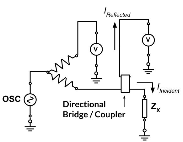
Network Analysis Method
The reflection coefficient is obtained by measuring the ratio of an incident signal to the reflected signal. A directional coupler or bridge detects the reflected signal, and a network analyzer supplies and measures the signals. Since this method measures reflection at the DUT, it is usable in the higher frequency range.
 Network Analysis Method
Automatically-Balanced Bridge Method
This method operates on the same fundamental principle as the bridge method and covers a broad frequency range from 1 mHz to 100 MHz, though it doesn't extend to very high frequencies. This technique is commonly used in many LCR meters.
In this method, the current Ix, which flows through the Device Under Test (DUT), balances with the current Ir flowing through the range resistor (Rr) via the I-V converter. The potential at the Low point is maintained at zero volts, creating a "virtual ground." The impedance of the DUT is then calculated using the voltage measured at the High terminal (Vx) and the voltage across Rr (Vr).

Auto-Balancing Bridge Impedance Method
Advanced Tools for Impedance Measurement
|
Technique |
Description |
Applications |
Benefits |
|---|---|---|---|
|
Time Domain Reflectometry (TDR) |
Used for characterizing and locating faults in cables, PCB traces, and connectors |
Characterizing and locating faults in cables, PCB traces, and connectors |
High resolution, precise fault location |
|
Impedance Spectroscopy |
Ideal for analyzing the frequency-dependent characteristics of materials and electrochemical systems |
Analyzing the frequency-dependent characteristics of materials and electrochemical systems |
Wide frequency range, detailed impedance profile |
|
On-Wafer Measurements |
Essential in semiconductor manufacturing for evaluating the impedance of microscale devices directly on the wafer |
Evaluating the impedance of microscale devices directly on the wafer |
Direct wafer-level testing, resource-efficient |
|
Vector Network Analysis |
Used in RF and microwave engineering for measuring the complex impedance of high-frequency components and systems |
Measuring the complex impedance of high-frequency components and systems |
High accuracy in amplitude and phase |

PCB Impedance Calculator in Action
Analyzing Impedance With OrCAD X
OrCAD X integrated impedance analysis workflows provide a solution for identifying and resolving real signal integrity issues. Designers can easily filter and select critical nets for impedance analysis, with results displayed on a color-coded scale from red to blue, indicating impedance levels. This allows for quick navigation to problematic traces by clicking on data points in a table view.
For instance, if an impedance discontinuity is caused by a split in the plane, adjustments can be made directly in OrCAD X, and the analysis can be rerun to verify the fix. This streamlined process aids designers in swiftly resolving signal integrity problems and accelerating their designs to production.
Cross-Section Editor Impedance Parameters
The cross-section editor within OrCAD X allows users to adjust parameters such as dielectric thickness to achieve desired impedance levels. These calculated values can then be applied to design rules within the Constraint Manager, where users can create and apply specific impedance rules to different layers and nets.
Now that you know about different impedance measurement circuits and how impedance is measured, try out OrCAD X to see just how its impedance analysis tools can help you in your designs. Unlock precise and efficient impedance analysis with OrCAD X today!