Home
Free Trial
Home
Free Trial
Read More
Content
Filter
10 results found
Featured
OrCAD X Capture with PCB Editor Tutorial 24.1
Featured
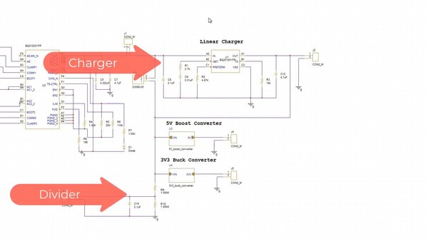
How to Manage PCB Design Variants in OrCAD X
Featured
How to Create an SOIC Footprint with OrCAD X Presto
Featured
How to Create a BGA Footprint with OrCAD X Presto
Featured
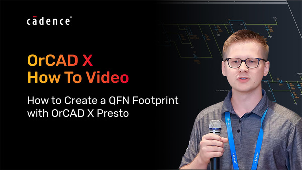
How to Create a QFN Footprint with OrCAD X Presto
Featured
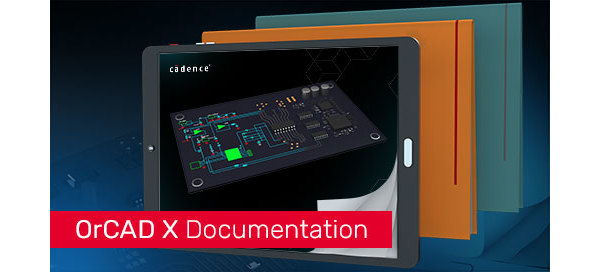
How to Easily Create Footprints for Your PCB Design
Featured
How to Import Schematic Symbols in OrCAD X Capture
Featured
How to Create Schematic Symbols in OrCAD X Capture
Featured
OrCAD X Design Flow Tutorial: Schematic, Simulation, and Layout
Featured
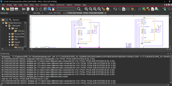
OrCAD X Error Codes
Featured
Products
None
OrCAD X
(10)
Content types
None
Technical Documents
(1)
Blog
(2)
Video
(6)
Product Documentation
(1)
Solutions
None
PCB Layout
(4)
Schematic Capture
(7)
Library Authoring & Management
(3)
Simulation & Analysis
(1)