OrCAD X PCB File Extensions Formats for Design and Simulation
Key Takeaways
-
File types like .DSN and .NET streamline schematic capture and layout workflows.
-
Extensions like .BRD and .DRC ensure compliance with design rules and manufacturability.
-
PSpice relies on formats like .lib and .cir for detailed circuit analysis.
This article discusses OrCAD X PCB file extensions for schematic, layout, simulation, and other advanced features.
Efficient PCB design in OrCAD X depends on mastering the various OrCAD X PCB file extensions that enable seamless integration of schematics, layouts, simulations, and manufacturing workflows.
For designers working with OrCAD X, understanding these file types and their specific roles is crucial to optimizing every stage of PCB development. Whether creating a schematic, simulating circuits in PSpice, or finalizing a board layout, each extension plays an essential part in achieving a streamlined workflow.
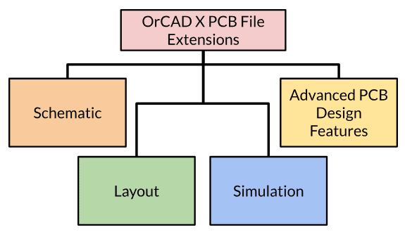
Schematic Related OrCAD X PCB File Extensions
Major PCB schematic file formats in OrCAD X
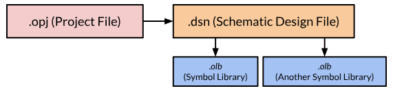
PCB design begins with creating a schematic, which forms the foundation for the entire design process. In OrCAD X, three key file types manage schematic information, each playing a distinct role in organizing, designing, and standardizing your project.
-
The .OPJ file serves as the central organizer for your PCB project. It acts as a container, linking all related schematic and layout files into a cohesive project. This structure facilitates seamless navigation between schematics, layouts, and simulations.
-
Maintains project structure.
-
Links schematic, PCB layout, and simulation data.
-
Acts as the backbone of the PCB workflow in OrCAD.
-
The .DSN file is the heart of OrCAD X Capture, storing the schematic design data of your project. It provides the foundation for PCB layout creation, capturing component symbols, netlists, and electrical connections.
-
Stores schematic data, including connectivity and component details.
-
Acts as the starting point for circuit design and layout translation.
-
Essential for creating accurate PCB layouts.
-
The .OLB file contains reusable component symbols, streamlining schematic creation by enabling drag-and-drop functionality. Custom .OLB libraries allow designers to ensure compliance with specific design requirements and standards.
-
Provides a library of reusable component symbols.
-
Saves time and effort in schematic design.
-
Supports customization for adherence to design standards.
Explore More About Schematic File Formats
This brief overview introduces the primary schematic file types in OrCAD X, but there’s much more to uncover. For an in-depth guide on schematic files, their advanced use cases, check out our dedicated piece on Schematic File Formats.
PCB Design Layout File Formats in OrCAD X
![PCB design file formats associated with PCB layout] [custom-made for blog](https://res.cloudinary.com/uf-552861/image/upload/v1736952673/pcb-layout_qhdxiz.png)
PCB design file formats associated with PCB layout
Design and Layout File Extensions
|
File Extension |
Purpose and Features |
|
.BRD |
- Physical board design |
|
.TCH |
- Basic technology parameters |
|
.TPF |
- Advanced stack-up and rules configuration |
|
.CMP |
- Component placement details |
|
.DRC |
- Design rule checking |
Pad, Footprint, and Connectivity File Extensions
|
File Extension |
Purpose and Features |
|
.PSM |
- Component footprint data |
|
.LIB |
- Logical-to-physical mapping |
|
.NET |
- Electrical connectivity |
|
.MNL |
- Manufacturing-specific netlist |
|
.DRA |
- Pad definition |
|
.PAD |
- Layer-specific pad implementation |
A Deeper Look into OrCAD X PCB File Extensions for Layout
While this table provides an overview of important PCB-layout-related design file formats, there are additional details, such as how specific file extensions like TCH and TPF interrelate or how LIB files interact with DSN files in the netlist generation process. To explore these aspects further, look to the PCB Design File Formats page.
OrCAD X PCB File Extensions for Simulation
PSpice simulations can be just as integral to the design process as the schematic editor, so it’s essential to understand the associated file types. It uses several file types to handle simulation data, models, and configurations. Below is an overview of the primary file extensions used in PSpice:
OrCAD X File Extensions in PSpice Simulation Software
|
File Extension |
Description |
|
.cir |
Circuit File: Contains the netlist and simulation commands for the circuit. It's a legacy format from PSpice's past. |
|
.lib |
Library File: Stores multiple model definitions, including .model and .subckt statements. Commonly used for organizing collections of device models. |
|
.mod |
Model File: Typically contains a single model definition. The .mod extension is not a standard part of SPICE but was adopted by companies like PSpice for convenience. |
|
.net |
Netlist File: Generated during the netlisting process, this file contains the netlist information for simulation. |
|
.als |
Alias File: Contains alias information used during simulation. |
|
.dat |
Data File: Holds simulation data, such as output variables and results. |
|
.inc |
Include File: Includes additional SPICE commands or model definitions in the simulation. |
|
.prb |
Probe Configuration File: Defines settings for the Probe waveform viewer, specifying which signals to display and how. |
|
.slb |
Symbol Library File: Contains graphical symbols for components used in schematics. |
|
.drt |
Design Rule Template File: Defines design rules and constraints for PCB layouts. |
|
.xmp |
Exported Model Parameter File: Contains parameters for exported models. |
|
.xnt |
External Netlist File: Represents external netlist data used in simulations. |
|
.xpk |
Package File: Includes packaging information for components. |
|
.sch |
Schematic File: Contains the schematic design data. |
|
.sp3 |
SPICE3 Model File: Contains SPICE3-compatible model definitions. |
|
.sip |
Signal Integrity Profile File: Contains data related to signal integrity analyses. |
Other Associated OrCAD X PCB File Extensions
![OrCAD X advanced features and associated filetypes] [image custom-made for blog](https://res.cloudinary.com/uf-552861/image/upload/v1736952673/advanced-features_zikxfo.png)
OrCAD X advanced features and associated filetypes
OrCAD X PCB file extensions are used for advanced capabilities as well, from rigid-flex to SI analysis. Below we’ve highlighted some key file extensions.
OrCAD X PCB File Extensions for Advanced Designs
|
Feature |
Associated File Extensions |
Description |
|
Rigid-Flex Design |
.brd, .step, .iges |
The .brd file includes rigid-flex design details, while .step and .iges formats are used for 3D representations and data exchange with MCAD tools. |
|
3D Engine |
.step, .iges |
3D models of the PCB are exported in these formats for visualization and mechanical integration. |
|
SI Analysis (Signal Integrity) |
.brd, .sip |
Signal integrity parameters are part of the PCB design file, with analysis reports saved in .sip format. |
Having an understanding of OrCAD X PCB file extensions is useful for working with such a powerful software. To see how OrCAD X can optimize your design workflow, visit the PCB Design and Analysis Software page or learn more about OrCAD X today.