Comparing Connectors and Cables to Flex Circuits
Before there were printed circuit boards, there were wiring harnesses with connectors at key intersections. Telecom is one of the industries that drove development of specialized connector types. For instance, ribbon cables made it possible to transport wider bus groups from one rack unit to another. They made rack assembly a snap.
These job-specific cables made it easier to integrate greater processing power using more lanes with better length matching and/or isolation than would be found with a normal wiring harness. Standardized cabling made electronics more modular. There are so many use cases for custom cables. Before going that route, it may be a good idea to find out what is already out there that addresses a similar requirement.
Common Wire Harness Solutions
Cable assemblies that are tailored for a specific use like USB, SATA, or Ethernet may have the right combination of power and signal pins to allow you to use a standard cable. A parallel ecosystem may already exist where you end up with a few spare pins. That would give you room to grow if needed.
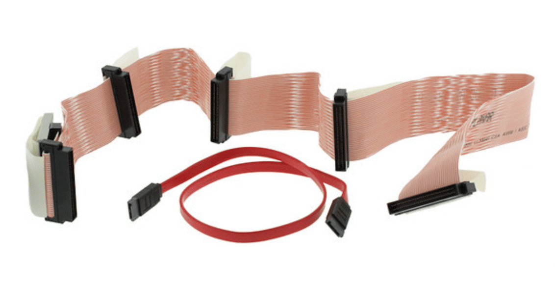
Figure 1. The ribbon cable can have numerous taps along its length or can be a simple end-to-end solution. Image Credit: Lori-Lyn Carreiro through EPEC.
Every header has a corresponding receptacle. There may be more than one receptacle to allow for different PCB thickness or some other attribute. These interrelationships are established in product catalogs. Connector companies are notorious for using tabular data. That is to say that one drawing will stand in for an entire line of connectors
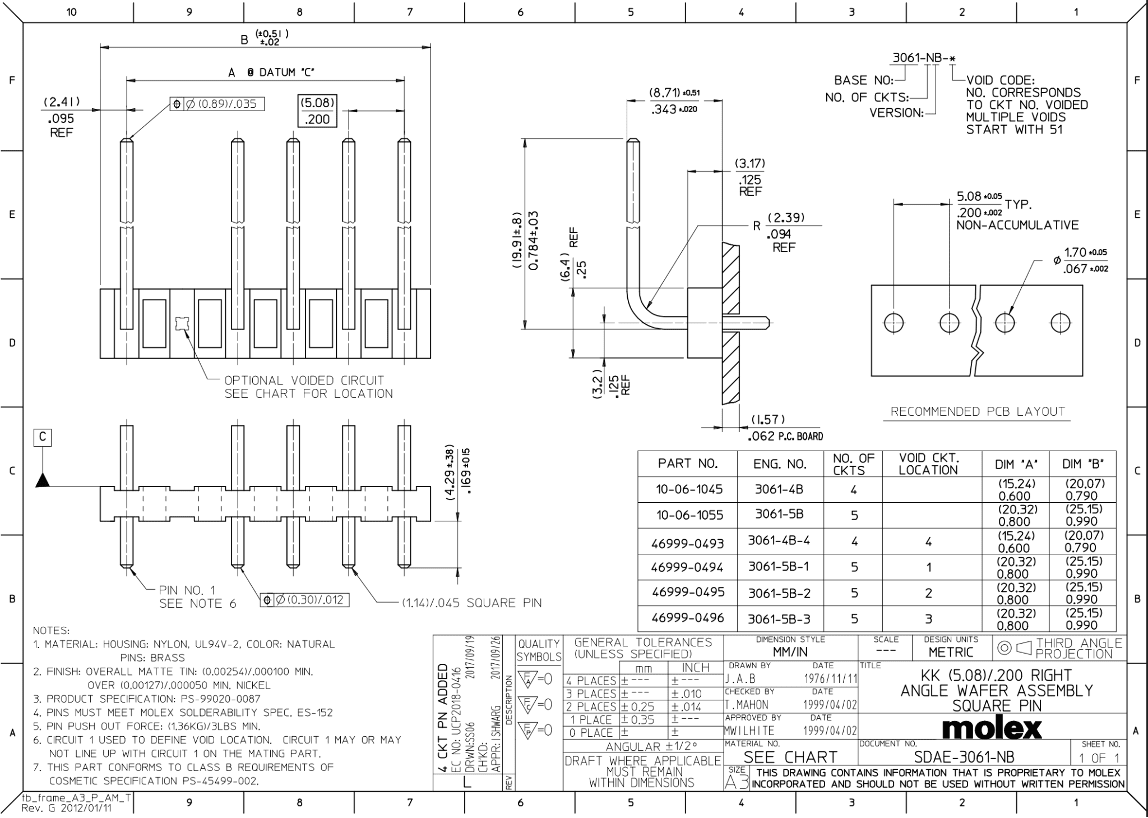
Figure 2. This is the simple type of connector where the only variable is removing one of the pins. You will have to figure out which pin will be pin one and which way the pins face. It gets interesting when there are more pins. This is more of an exception that proves the rule. Image Credit: Molex
The vendor part number will be segmented into several sections with each character defining a different attribute. It might start with the connector family and could include the length, width, number of rows and so on.
No two companies use the same formula nor are they compelled to work in harmony with each other. What they have in common is that each section of the part number will require you to find a different page of the part catalog to determine what the characters of the part number mean. If it's any consolation, the footprints are usually available for ECAD implementation.
Things to Remember When Placing Connectors
- There has to be room for human fingers to get ahold of the connector for insertion and extraction. In some cases, a tool needs space to tighten a fastener.
- PCB routing from the connector should be on an exposed surface layer so that cut-and-jump repairs are facilitated.
- The wiring should have sufficient service loop make/break connections; about one inch of extra wire at a minimum for rework should be sufficient
- The head room needs to be accounted for on vertical launch connectors while also accounting for room along the edges for engaging side-launch connectors. Again, consider reparability.
- Connector polarity and reference designator should be clearly marked on the PCB and on the assembly drawing. If room allows, VOUT and other important pins should be marked.
- Electrostatic discharge (ESD) should be managed to minimize the incursion of high voltage spikes into the PCB.
- While not an active component, connectors are often near their limits in terms of thermal dissipation. Provide copper pour and GND vias where possible.
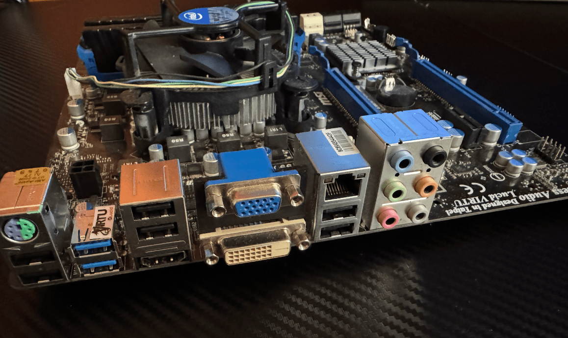
Figure 3. Gamers have all of the luck when it comes to interconnections. Different types are combined into little connector condominiums for this PC motherboard. The rest of the board bristles with expansion slots and other vertical-launch connectors. Image Credit: Author.
Flex Circuits - The Ultimate Solution
When all else fails, we have the bespoke solution in flexible printed circuit (FPC) technology. While modified semi additive process (mSAP) geometry is available in some factories, most of the ones doing flex circuits have no problem with 25 micron trace/space geometry. The rest likely will be comfortable with 50 micron traces. Like everything else, there are trade offs to consider with FPCs
The freedom to bend, twist and fold the Flex comes with responsibility for the material stack-up. Areas with components attached are going to want a stiffener bolstering their real estate from below. Stainless steel is a preferred stiffener but FR4 and even polyimide are used depending on application.
Different Zones For Different Outcomes
Even when an area does not have components mounted, we still have to manage bends that get formed during assembly as well as any zones that are subject to frequent flexing. Design rules often include via keep-out areas, especially near dynamic flex regions. A mesh would be used in place of a solid shape for power and ground. Some areas may have glue removed from between the layers to create a loose leaf flexibility.
In addition to the polyimide dielectric and annealed copper metalization, we also contend with the soldermask layer which tucks under the coverlay. The coverlay basically goes wherever there are no parts. It matches the outline. Polyimide stiffeners would also follow the flex outline while FR4 and steel stiffeners would be a little smaller than the main flex outline.
There is also a potential EMI suppression layer that has to tie to GND at key locations. The coverlay would have to be cut away while copper pour would fill in if it was generally a mesh. The stack-up for a flex circuit is complex and tricky to pin down fully.
All of these variables will revolve around the mechanical definition; the board's outline and interconnect control drawings. Most flexes are going to have straightforward routing even if it's on a narrow pitch. Curved traces rule the day except for in the bend regions where we try to keep them straight.
To Flex or To Connectorize?
In spite of all of the possibilities unleashed with Flex Circuits, many of them end up being glorified connector cables. There's usually a connector at two or three ends and not much else in terms of components. The drama in these situations is around the frontier of the stiffened zones. It's another region where we do not tolerate vias and we want the traces to be as uninteresting as possible; straight on through.
As mentioned above, the special feature of flex circuits is to conform to any shape necessary. When connectors can fill the gap, it is so much better for the timeline. Using 1:1 connections where the pins are all the same at both ends means that a stacking connector might be the intra-board solution. There are a huge number of off-the-shelf solutions for connectors and cable assemblies. Let your innate synaptic connections guide you to the best interconnect solutions.