High-Speed Trace Routing Guide in OrCAD X
Key Takeaways
-
Optimize routing efficiency with Add Connect, assisted Hug/Shove modes, and trace width adjustments for precise PCB routing.
-
Editing tools like Cut Traces and Split Via Stacks allow seamless circuit modifications without affecting overall connectivity.
-
Ensure error-free PCB design by maintaining DRC compliance and enhancing signal integrity with OrCAD X’s powerful routing automation features.
Trace routing is the process of creating conductive pathways (traces) on a PCB to connect electronic components. Proper routing minimizes signal integrity issues, reduces electromagnetic interference (EMI), and ensures the board functions reliably. In modern PCB design, high-speed trace routing is especially important due to the increasing demand for faster data transmission and complex circuit layouts. This article will explore the practical implementation of high-speed trace routing within OrCAD X, leveraging its routing capabilities.
Basic High-Speed Trace Routing in OrCAD X
Basic routing in OrCAD X provides tools to efficiently connect components while maintaining design rule constraints. Features like Add Connect, trace width adjustments, and assisted routing modes, help designers create clean and reliable PCB layouts.
Using the Add Connect Command
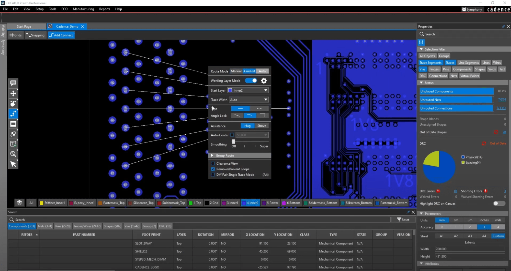
The Add Connect command OrCAD X Presto covers most routing needs. To begin, select Add Connect from the floating toolbar. A helper window will appear on the canvas, providing property adjustments for the command's behavior. You can hide or display this window by pressing the highlighted tab at the top of the canvas or using the hotkey "X" for quick access.
For high-speed trace routing, time alignment of distinct signal paths is needed for signal integrity and system functionality, which can be achieved by precise trace length matching. Smoothing traces help create a more uniform, predictable, and reliable electrical and mechanical environment for your signals. By default, manual mode allows routing without assistance. However, designers must be mindful of Design Rule Check (DRC) errors. If a trace violates constraints, it will turn red and flag a DRC error, though it can still be placed. The following tables outline the steps to apply the Delay Tune and Custom Smooth features.
Step-by-Step Guide for Routing and Delay Tuning in OrCAD X
|
Steps |
Delay Tuning in OrCAD X |
|
1 |
Select Route > Delay Tune from the menu. |
|
2 |
In the Options panel, set Gap to 3x Width and Corners to 45°. |
|
3 |
Select the shorter routed connection between two pins. |
|
4 |
Click and move the cursor away from the trace to add delay tuning to equalize the trace lengths. |
|
5 |
When finished, right-click and select Done. |
|
6 |
Select the whole trace, right-click, and select Fix to lock the trace and prevent it from being edited. |
|
|
Smoothing Traces in the Design |
|
1 |
Select Interconnect > Manual Routing > Slide from the Design Workflow or use Route > Slide. |
|
2 |
Click a trace segment to slide it, then click again to place it. |
|
3 |
Select Route > Custom Smooth from the menu. |
|
4 |
Highlight the entire design, then right-click and select Done to apply smoothing to all traces. |
Adjusting Trace Width and Constraints
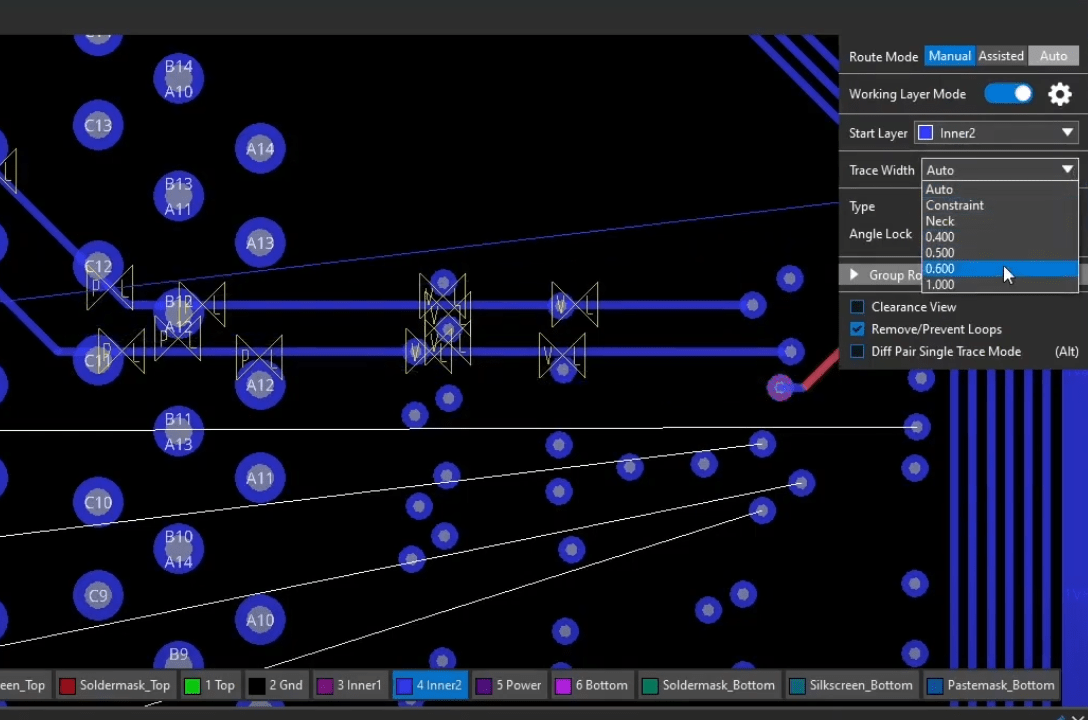
Trace width can be adjusted via a dropdown menu or by manually entering a value. There are three width modes:
-
Auto: Uses constraint values for width.
-
Constraint: Inherits width from an existing trace.
-
Neck: Determines width based on settings in the Constraint Manager.
Cornering and line behavior can be adjusted using sliders, allowing features like arc routing and free-angle corners for smoother routing. To find optimal routing paths, Clearance View can be enabled. This visual aid draws bumpers around copper features based on spacing constraints.
Assisted Routing: Hug and Shove Mode
For automated routing assistance, OrCAD X provides Hug Mode and Shove Mode:
-
Hug Mode: Keeps traces as close as possible to copper features without violating constraints. When combined with smoothing, the routing process is optimized by reducing unnecessary vertices.
-
Shove Mode: Automatically moves traces or vias to create a valid routing path. By default, only traces can be shoved, but vias can also be enabled. Since objects move dynamically, it's recommended to turn off Clearance View when using Shove Mode.
Advanced High-Speed Trace Routing in OrCAD X
For more complex PCB designs, OrCAD X offers routing capabilities like Cut Traces and Split Via Stacks. These features allow designers to make precise modifications without disrupting the entire layout, improving workflow efficiency and ensuring high-speed signal integrity.
Cut Traces Command (Scalpel Cut Tool)
The Cut Traces feature, available in OrCAD X Presto 24.1, allows designers to precisely cut through a trace or multiple segments while retaining net connectivity where applicable. This tool is particularly useful for isolating a section of a circuit for modifications without affecting the rest of the design.
How to Use Cut Traces
-
Located in the same command group as "Slide".
-
The Cut Width option defines the width of the removed section.
-
To execute, select start and end points, and the selected trace segment will be removed.
Splitting Via Stacks While Sliding Traces
A major improvement in OrCAD X 24.1 is the ability to split via stacks using the Slide command. When sliding a trace with stacked micro vias, right-clicking will now display an intuitive UI pop-up for selecting the appropriate via to split. Users can also preview the changes in the 3D canvas.
How to Enable Split Stack
-
Navigate to Edit > Preferences.
-
Select the Shortcuts menu.
-
Go to the Commands tab.
-
Enable Split Stack in the right mouse button menu for the Slide Command.
Mastering high-speed trace routing in OrCAD X is essential for designing high-performance PCBs. Whether you're refining basic connections or leveraging advanced tools like the Cut Traces command and Split Via Stacks, OrCAD X provides the customization you need. Start optimizing your designs today—explore the OrCAD X platform and register for the OrCAD X Free Trial to test the powerful routing features and take your PCB layouts to the next level!
Leading electronics providers rely on Cadence products to optimize power, space, and energy needs for a wide variety of market applications. To learn more about our innovative solutions, subscribe to our newsletter or our YouTube channel.