Exploring Flex PCB Current Carrying Capacity
Key Takeaways
-
Polyimide flex PCBs are known for their heat resistance and flexibility and are well-suited for high-current applications. Adjustments in trace width, copper thickness, and copper type (like rolled annealed vs. electro-deposited) are crucial for managing flex pcb current carrying capacity.
-
Factors such as operating temperature, the number of parallel traces, and the ambient environment significantly affect the heat dissipation and current capacity of flex PCBs.
-
The utilization of tools like OrCAD X, which supports features like 3D engine updates, cross-section editors, and specific rigid-flex DRCs, helps in optimizing flex PCB designs.
Oftentimes, rigid-flex PCBs must carry substantial amounts of currents through connectors.
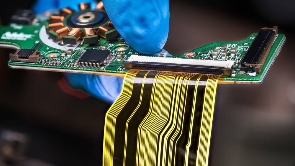
Common polyimide flex PCBs, identifiable by their amber color, withstand heat comparable to or greater than FR4 boards, with current capacity determined by copper thickness and trace width. They typically feature a Comparative Tracking Index (CTI) above 600 volts, making them suitable for applications up to 300 volts DC. A higher CTI value indicates a material's higher resistance to electrical breakdown along its surface under moist or contaminated conditions.
Achieving high current levels like 30A can compromise flexibility due to necessary increases in material thickness. Material selection, required flexibility, and other factors discussed below primarily influence flex PCB current carrying capacity.
Factors Influencing Flex PCB current Carrying Capacity
|
Factor |
Influence on Current Carrying Capacity |
|
Trace Width and Thickness |
Wider and thicker traces offer lower resistance, enabling them to handle higher currents by reducing excessive heat generation. Lower bend capabilities may necessitate adjustments in conductor width to accommodate design limitations, impacting current handling. |
|
Copper Weight |
Heavier copper layers provide lower resistance, allowing for the handling of higher currents compared to thinner layers, but they also have increased PCB rigidity. Materials like electro-deposited copper used in surface plating can lead to micro-cracks due to lower bend capability, lowering capacity. |
|
Temperature Rise |
Excessive temperature degrades performance through increased resistance. Lower bend capability leads to stress and poor heat dissipation, further elevating temperatures and affecting performance. |
|
De-Rating Factors |
Conditions like conductor thickness over 3 oz require current capacity de-rating. Lower bend capabilities increase resistance and heat generation, necessitating further de-rating in designs. |
|
Copper Foil Type |
Variations in conductivity among copper foil types affect capacity; high-quality foils typically support better current handling. |
|
Trace Length |
Longer traces increase resistance and heat, reducing capacity; shorter trace lengths optimize current handling. |
|
Operating Environment |
Ambient temperature and airflow influence heat dissipation and capacity; higher temperatures decrease this capacity. |
|
Number of Parallel Traces |
Distributing current across multiple parallel traces increases total capacity and prevents the overloading of individual traces. |
|
Techniques like etching and plating impact trace dimensions and copper uniformity, affecting capacity; precise methods enhance capabilities. |
Using a Nomograph
Engineers use a current rating nomograph, a TYPE of graphical calculator, to estimate flex PCB current carrying capacity by considering parameters like trace width, copper thickness, and temperature factors. This tool includes axes for various parameters connected by lines.
Users draw lines between points representing specific values, such as trace width and copper thickness, and extend these lines toward desired temperature rise values. The intersection point on the current axis gives the current rating estimate. While helpful, this nomograph provides only an approximate starting point. Designers must also account for factors like parallel trace configurations, operating conditions, and manufacturer datasheets and industry standards.
Current Carry Capabilities vs. Current
The flexibility demands of flex circuits restrict the typical copper thicknesses offered by material suppliers to 2 OZ or less. Should a design necessitate copper thicker than 2 OZ to manage current safely, three alternatives can be considered:
Pros and Cons of Alternatives for Thicker Copper on Flex PCBs
|
Option |
Pros |
Cons |
|
Special Order Materials |
Utilizes adhesive-less construction to reduce flex thickness |
Costly; requires longer lead times |
|
Increase Copper Thickness With Surface Plating |
Achieves up to 3 OZ copper (2 OZ base + 1 OZ plated) |
Plated copper is electro-deposited and less flexible |
|
Manufacture Core Material In-House |
Uses only rolled annealed copper without plating |
Increases core thickness due to necessary adhesive layers |
Designs requiring controlled impedance add to the flex thickness and diminish bending capabilities. To meet specific impedance requirements, thicker cores are essential. Due to the increased copper thickness, the need for wider line widths further expands the core thickness.
OrCAD X for High Current Flex PCBs
OrCAD X has a variety of features, making it well-suited to support flex PCB designs with particular current carrying capabilities.
OrCAD X Tools and How They Aid in Rigid-Flex PCB Design
|
OrCAD X Tool/Feature |
How It Helps in Rigid-Flex PCB Design |
|
3D Engine Updates |
Enhances visualization of rigid-flex configurations, allowing designers to optimize assemblies in constrained spaces and reduce errors prior to manufacturing. |
|
Cross Section Editor |
Enables precise setup of multi-layer stack configurations tailored for specific rigid and flex regions, crucial for complex rigid-flex designs. |
|
3D Exports |
Provides capabilities to export detailed 3D models of the board, which can be used for comprehensive ECAD/MCAD analyses, including visualizing board flexures. |
|
IDX Import |
Supports seamless integration of mechanical and electrical design data, improving the accuracy of flex zones and bend definitions in the PCB design. |
|
Design and Assembly Verification (Interactive 3D) |
Offers interactive 3D visualization to verify assembly and fit within enclosures, adjust solder mask transparency, and resolve collisions, thereby reducing revisions and fabrication costs. |
|
Specific Rigid-Flex DRCs and Constraints |
Applies design rule checks (DRCs) and constraints specific to rigid-flex PCBs, ensuring compliance with manufacturing standards and enhancing the reliability of the final product. |