CMOS Power Calculation
Key Takeaways
-
The CMOS circuit has two states: the CMOS gate is not switching, or the CMOS gate is switching.
-
Static power is the power lost in the CMOS circuit due to the flow of leakage current through the transistors when the circuit is inactive.
-
Dynamic power is consumed by the CMOS circuit when it performs valuable work during the active mode of operation.
The factors influencing the CMOS power consumption are input rise time, input voltage level, output loading effects, power dissipation capacitance, etc.
CMOS technology was developed to minimize the power consumption of devices, thereby improving their reliability. However, including CMOS technology over other technologies doesn't guarantee low power consumption. It is essential to know about the CMOS power calculation and the factors affecting CMOS power.
Some factors influencing CMOS power consumption are input rise time, input voltage level, output loading effect, power dissipation capacitance, etc. We will look at the different types of power consumption in CMOS and how to perform CMOS power calculations.
CMOS Technology
After the invention of the transistor, the vacuum tube was replaced due to transistor advantages like low power consumption, small size, low-temperature operation possibilities, fast responses, etc. Transistors became the building block of electronic circuitry, especially for integrated circuits or chips.
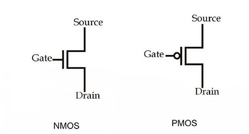
The solid-state metal-oxide-semiconductor field effect transistor (MOSFET) is the fundamental element of any microchip. Typically, ICs or microchips consist of negative MOSFETs (NMOS) and positive MOSFETs (PMOS).

The NMOS transistor source and drain terminals are heavily doped with arsenic (As) or phosphorus (P). The body is moderately doped with acceptor ions of elements such as Boron (B). Unlike NMOS, PMOS is heavily doped with Boron at the drain and source. The body of the PMOS transistor is moderately doped with P ions.
The combination of PMOS and NMOS is powerful, with characteristics such as low static power, higher noise immunity, etc. NMOS and PMOS are used in electronic circuits due to the features mentioned above. When the combination of PMOS and CMOS are used together in an electronic circuit, they are called complementary metal-oxide-semiconductors or CMOS.
CMOS Power Calculation
CMOS circuits have two states:
-
The CMOS gate is not switching. It is in a steady-state or static condition (non-charging state).
-
The CMOS gate is switching. It is in a dynamic condition (charging state).
Depending on the operation condition of the gate, the CMOS circuits consume power in two ways - statically and dynamically.
Static Power
When the CMOS is in a static or steady state condition with the gate not switching, all inputs remain at the valid logic levels, and the circuit is non-charging. The power consumed in this condition is called static power consumption.
Otherwise, static power is the power lost in the CMOS circuit due to the flow of leakage current through the transistors when the circuit is inactive or not operating.
P static = V cc * I cc(1)
Vcc is the voltage applied to a logic IC and Icc is the static supply current of the IC given as per the datasheet.
Dynamic Power
When the CMOS is in dynamic condition with gate switching, all inputs change logic levels and the circuit is in its charging state. The power consumed in this condition is called dynamic power consumption. The charging and discharging of the capacitive output load, which is common in all logic circuits, aggravates the dynamic power consumption.
Otherwise, dynamic power is the power consumed by the CMOS circuit when it performs useful work during the active mode of operation.
Dynamic Power Bifurcation
The dynamic power dissipation in the CMOS circuit may be due to two conditions:
|
Switching Power |
Dissipated when switching activities occur at the nodes. |
|
Short-Circuit Power |
Consumed by the CMOS circuit when both NMOS and PMOS transistors are conducting current during signal transitions. |
Switching Power: The change of the logic state makes a switching activity (SA). The probability that the circuit node switching between the logic states 1 and 0 can be considered as a switching activity. The switching power Pswitching is high, as the CMOS circuit switches at a high frequency. The toggling between high and low logic increases, which in turn increases the activity factor or switching activity.
P switching = f sw * C L * V cc 2 (2)
fsw is the switching frequency and CL is the dynamic effective capacitance.
Short-circuit Power: The PMOS and NMOS transistors are simultaneously switched or conducted for a short duration of time when the logic changes its state. The simultaneous condition of PMOS and NMOS makes the CMOS circuit short-circuited for that short time, resulting in short-circuit power denoted by Pshort-circuit.
Pshort-circuit = TSC * I peak * V cc
Tsc is the shortcut-circuit time period and Ipeak is the peak current.
Considering the parts of dynamic power, it can be mathematically expressed as:
P dynamic = P switching + P short-circuit (4)
Total CMOS Power Calculation
The CMOS total power is the summation of static power and dynamic power. The total power of the CMOS circuit can be mathematically represented as follows:
Ptotal = P static + P dynamic (5)
Ptotal is the total CMOS power, Pstatic is the static power consumed by the CMOS, and Pdynamic is the dynamic power consumed by the CMOS.
While calculating CMOS power, the effect of capacitance during switching influences the value of the dynamic power and increases the power dissipation. In most cases, the CMOS power calculation requires the measurement of the capacitance as well. Cadence OrCAD can help you in calculating the power dissipation of integrated circuits or microchips.
Leading electronics providers rely on Cadence products to optimize power, space, and energy needs for a wide variety of market applications. If you’re looking to learn more about our innovative solutions, talk to our team of experts or subscribe to our YouTube channel.