Voltage Stability in Power Systems: Key Concepts and Analyses
Key Takeaways
-
Voltage stability in power systems can be impacted by various disturbances; including faults, load changes, equipment failures, and weather events.
-
Instability can cause severe issues like loss of load, cascading outages, and the loss of synchronism in generators.
-
Dynamic analysis provides time-domain insights critical for addressing fast voltage collapse scenarios, while static analysis offers quicker, algebraic equation-based evaluations of system stability.

High Voltage Transformer Used on the Electrical Grid
Voltage stability in power systems involves sustaining stable voltages at all bus points within the system after experiencing a disturbance. It ensures that the voltage throughout the system stays within a specified range under both normal and disturbed conditions. It can drop for just a few seconds to an extended longer period of time. Instability can manifest as a progressive decrease or increase in the voltages at certain buses.
Sources of Voltage Instability in Power Systems
|
Disturbance Type |
Description |
|
Faults |
Sudden voltage drops or complete loss due to system faults. |
|
Switching Operations |
Circuit breaker operations can cause voltage transients affecting stability. |
|
Load Changes |
Rapid changes, such as starting large motors or tripping loads, can destabilize the voltage. |
|
Equipment Failures |
Failures in generators or transformers can lead to reliance on backup power or network reconfiguration. |
|
Weather Events |
Severe weather can damage equipment or disrupt power flow, leading to voltage disturbances. |
Voltage Stability in Power Systems
In power systems, voltage at any point must remain within limits set by regulatory bodies and standards organizations to ensure safe and acceptable levels for properly operating connected equipment. Normally, voltage should stay constant or vary slightly around a nominal value, with fluctuations primarily driven by changes in load demand.
Outcomes of Voltage Instability
Loss of load in an area often involves the tripping of lines and other components, potentially leading to cascading outages. Additionally, some generators may lose synchronism due to these outages or when operating conditions exceed excitation current limits. Several types of equipment can exacerbate voltage instability:
- Induction motors
- Distribution voltage regulators
- Tap-changing transformers
- Thermostatic loads (space heaters, fridges, water heaters, etc.)
During normal operation, the latter three devices aim to restore the power consumed by the loads, but this characteristic can lead to problems in contingency situations. A run-down situation occurs when load dynamics attempt to restore power consumption beyond the capacity of the transmission network and connected generation, ultimately causing voltage instability.
Security vs. Instability
A voltage security problem might manifest as low voltage, where the voltage level falls below a predefined range; however, low voltage does not inherently indicate voltage instability. Voltage instability is characterized by an uncontrolled decline in voltage. It's important to note that even if the voltage remains within the normal range, it does not guarantee continuous voltage security.

Space heater, a type of thermostatic load.
Short-Term Voltage Instability
Short-term voltage stability occurs when large disturbances, such as multi-phase faults near load centers, decelerate motors. This scenario can lead to motors drawing significantly high currents in an attempt to reaccelerate after fault clearing, which might include transmission outages. If the power system is weak, these motors may stall, leading to a massive loss of load, which in turn could cause area instability and potential voltage collapse.
This type of voltage stability is particularly associated with induction motors, like those found in residential air conditioners and heat pumps. These motors experience slowing of low-inertia air-conditioner compressor motors during short circuits, necessitating high currents akin to starting currents. If these motors stall, it hampers rapid voltage recovery post-short circuit clearing. Typically, compressor motors are only tripped after overheating, which might take 3 to 15 seconds post-stalling. This can lead to cascading motor stalling within a few seconds.
Long Term Voltage Instability
Long-term voltage stability involves significant disturbances, such as system faults or loss of a generator, followed by a process of load restoration or change within a timeframe of 0.5 to 30 minutes. The network's capacity to efficiently transfer power from the point of production to consumption significantly impacts voltage levels, primarily due to reactive power transfer, which leads to voltage drops and reactive power losses (I2X), primarily from active power transfer.
The overall stability of the system is determined by its ability to control voltages after large disturbances and the interaction between load characteristics and the control and protection systems.
Voltage Stability Analysis
Voltage stability involves maintaining a consistent voltage profile under different conditions. Analytical tools such as load flow analysis, transient stability analysis, and voltage stability margin analysis are utilized to predict potential issues and develop mitigation strategies. The objective is to detect and rectify instability before it causes system problems.
Static Analysis
The static approach to power system analysis utilizes static models of power system components and is particularly crucial during the operation and planning phases. This allows for preparing an adequate reactive power management plan to address various contingencies that may arise during system operation.
It involves algebraic equations to effectively analyze the viability of specific operating points within the power system. The static approach also provides critical information, such as sensitivity or stability margins. Being much faster than dynamic methods, it enables analyzing power systems under a wide range of conditions. Static simulation uses a power flow program for approximate analysis and screening:
-
P-V Curves: outline the relationship between the active power delivered and the voltage at the load terminals, and is exemplified in the image below. Indicates maximum power deliverable by the system at the tip of the "nose." As power demand increases, the system moves from a high power and voltage point towards this maximum limit; exceeding this point without adequate reactive power reserves can lead to a voltage collapse.
-
Q-V / V-Q Curves: Illustrates the relationship between reactive power (Q) and voltage (V) at system buses. Reveals how voltage levels respond to changes in reactive power demand, pinpointing the maximum reactive power that can be managed before voltage collapse.

Rough shape of typical power-voltage curve
Dynamic Analysis
The dynamic approach utilizes time-domain simulations to explore the mechanisms behind voltage collapse, including the reasons and processes. Dynamic methods assess the impact of dynamic loads, on-load tap changers (OLTC), and generator overexcitation limiters on voltage stability.
This type of analysis offers the most accurate depiction of the system's time responses, making it essential for addressing fast voltage collapse scenarios triggered by events like loss of generation or system faults. Dynamic simulations often do not provide insights into the sensitivity or stability margins and require detailed dynamic models of system components and parameters, making the process time-consuming.
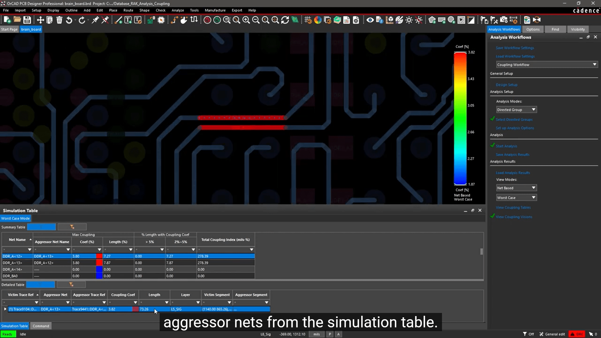
Running the coupling analysis workflow in OrCAD, aids in identifying and minimizing unwanted signal interference on your PCBs.
Beyond large-scale infrastructure, the reliability of power systems also hinges on circuit board components that manage power flow and protect against fluctuations. Utilizing a tool like OrCAD X is essential for designing PCBs that uphold these critical functions, optimizing them for the demands of power distribution networks and enhancing overall system stability.
Leading electronics providers rely on Cadence products to optimize power, space, and energy needs for a wide variety of market applications. To learn more about our innovative solutions, talk to our team of experts or subscribe to our YouTube channel.
Leading electronics providers rely on Cadence products to optimize power, space, and energy needs for a wide variety of market applications. To learn more about our innovative solutions, talk to our team of experts or subscribe to our YouTube channel.