03 - How to Set up OrCAD X Capture CIS
Setting up the OrCAD X Component Information System (CIS) involves the following tasks:
Creating a Part Database
The first step in creating a part database is to determine the properties to include for each part. Typical properties in a part database include part number, part description, tolerance, rating, speed, timing parameters, PCB footprint, manufacturer, and cost. CIS supports an unlimited number of properties, so you can include as much information in your part database as you want. Capture CIS includes:
Part Properties
There are no restrictions on database table property names. Also, the names you use in the database can be different than the property names you assign to the placed parts.
For example, you can name the Part Number property My Company Part Number. Also, you may call a property Tolerance in the database and Tol on the placed part.
Database property types and placed-part property names are defined during database configuration.
Do not use the same property name more than once. For example, if you have two manufacturer columns in your database, call them Manufacturer 1 and Manufacturer 2.
When you transfer a property, that property is included in the schematic as an attribute of the placed part. Normally, you transfer properties that are required by CIS (such as Part Number and Schematic Part), used in the design process (such as Value, Tolerance, and Rating), or needed for use by other software products (such as PCB Footprint). Properties that aren’t transferred can still be included in a bill of materials report.
Parts in your database must include all of the properties. Any of the optional properties may also be added. Recommendations on whether to transfer properties to your design are included in both tables. Properties recommended for transfer to the design are either likely to be required for netlisting or are generally needed on printouts of the design.
You may want to look at the sample part databases provided with CIS. The SQLite database, BENCH.DB, is provided in the \TOOLS\CAPTURE\SAMPLES folder. As you read this section, refer to this sample to get a better understanding of how to set up your part database.
Note that your database can also contain mechanical (non-electrical) parts. However, you must not allow users to add mechanical parts to the database whose schematic representations (symbols) have pins. If mechanical parts with pins are placed in a design, they will invalidate netlists generated from that design. Capture CIS allows you to generate a BOM that lists all the mechanical parts and assemblies associated with an electrical part in your design.
Required Part Properties
The following table shows the required part properties:
| Property | Description | Transfer to Design |
|---|---|---|
|
Part Number |
Required to identify the part in association with the CIS Part_Number property type. This property is required by the part manager and the bill of materials report. CIS lets you enter more than one database part with the same number in the database. However, you should use a unique part number for each part and have no duplicate part entries in your database. |
Required |
|
Part Type |
Identifies the part type. The Part Database Explorer uses this property to define the part database folder hierarchy. Use this property to facilitate part searches. Typical contents are resistor, resistor\fixed, capacitor, capacitor\electrolytic, IC, IC\Memory\SRAM, connector, and so on. The levels of the hierarchy are defined using the backslash (\) character (or any character you define in the configuration). You can define any number of levels in the hierarchy. This property is also used by the Part Reference Associations option. This property is case-sensitive. Make sure you use uppercase-lowercase conventions consistently when entering values for this property. |
No |
|
Schematic Part (Symbol) |
Identifies the part name. This property is required to use the Place Database Part command. Only the part name is necessary if the part is stored in the same directory as the custom schematic part libraries (.OLB files) that you configure in Capture. However, to avoid placing an identically named part, include the library name, a backslash (\), and then the part name. Examples include: DISCRETE\CAP In addition, you can use the explicit path so CIS can locate an unconfigured library. For example: C:\MYLIB\DISCRETE\CAP Do not directly reference the schematic part libraries that are supplied with Capture CIS (resource libraries). Because the resource libraries in your installations of Capture CIS are often changed during upgrades to new software versions, the library names and paths in your database can be made invalid. Instead, create your own custom libraries by renaming the resource library files or copying individual parts from the resource libraries to your custom libraries. |
Automatic |
|
You can also assign multiple schematic part names to a single part. Use the same format for each name and separate each one with the multi-value delimiter (by default, a comma). For example: DISCRETE\CAPACITOR NON-POL, DISCRETE\CAP NP, DISCRETE\SMALL CAP The default value of the multi-value delimiter is a comma. However, when setting administrative preferences during database configuration, you can change the character CIS recognizes as the delimiter to a colon, semi-colon, question mark, or vertical bar. Then, when you update your design’s part status, CIS can approve and make current a schematic part which has several acceptable names. Also, if a database part has several different valid schematic parts, you will be able to choose any one of them when you are placing parts from the database parts window. All the configured schematic parts for the database part will be available from a drop-down list under the Schematic Part property name. CIS locates the Capture library using the following set of prioritized rules:
If no libraries are included specifically in your Capture design, CIS searches the LIBRARY directory in your Capture installation directory. |
||
|
Value |
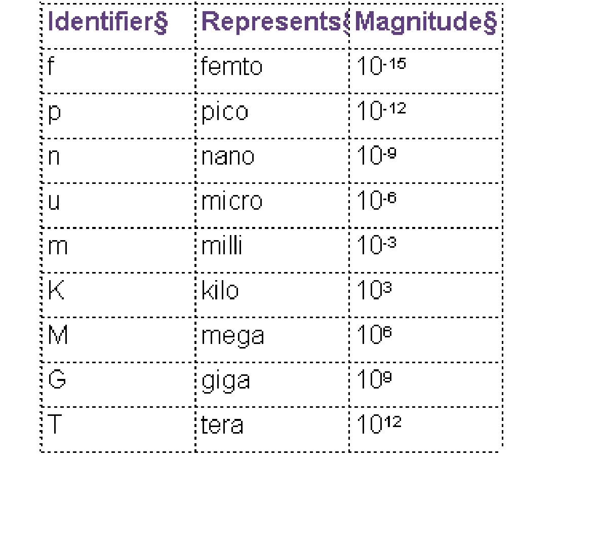
The part value. Examples are 1.2K, 10.0uF, and 74ALS374. CIS supports the use of common magnitude identifiers (such as K and uF). The database query uses intelligent unit conversion to interpret common magnitude identifiers in part definitions, since entries in part databases are often inconsistent (for example, the Value for a 2.7K resistor can be 2.7K, 2,700, 2.70K, 2.700K, 2700.0, 0.0027M, etc.). Unit suffixes (such as F for farads or H for henries) are ignored in translation. The magnitude identifiers supported in CIS include: |
Required |
Optional Part Properties
The following table shows the optional part properties:
| Property | Description | Transfer to Design |
|---|---|---|
|
Availability |
Number of the parts in stock at your company. |
Not recommended |
|
Data Sheet |
The name of the detailed datasheet for this part. Select the Browsable check box in the configuration for CIS to automatically launch the appropriate browser for this property. Examples include: 74ALS374.PDF, and RES1K1/4W.DOC. You can browse any format you want. CIS uses the application assigned to that file extension in your Windows registry. (Extension assignments are managed in the Windows Explorer). For example, a .DOC entry might cause CIS to launch Microsoft Word, and a URL entry might cause it to launch your default web browser. CIS uses the PATH environment variable and the current working directory to find the specified document. |
Not recommended |
|
Description |
A brief description of the part. |
Not recommended |
|
Distributor |
Name of part distributor. |
Not recommended |
|
Distributor Part Number |
Part number used to order from the distributor. |
Not recommended |
|
Manufacturer |
Name of part manufacturer. |
Not recommended |
|
Manufacturer Part Number |
Part number used to order from the manufacturer. |
Not recommended |
|
PCB Footprint |
The PCB footprint name (from the footprint library) assigned to a part. Unlike Schematic Part property names, you cannot use directory paths for libraries with PCB footprint names. If you use a path with a PCB footprint name, the footprint will not display in the CIS explorer’s footprint window. You can assign multiple PCB footprints to a single part by entering them in the part’s footprint field in your part database and separating each footprint name with the multi-value delimiter. The default value of the multi-value delimiter is a comma. However, when setting administrative preferences during database configuration, you can change the character CIS recognizes as the delimiter to a colon, semi-colon, question mark, or vertical bar. Then, when you update your design’s part status, CIS can approve and make current a schematic part which has several acceptable footprint names. Also, if a database part has several different valid PCB footprints, you will be able to choose any one of them when you are placing parts from the database parts window. All the configured PCB footprints for the database part will be available from a drop-down list under the PCB Footprint property name. |
Recommended |
|
Price |
Defines the part price. Use this information when selecting parts to design for cost. Include this property in reports to get a cost roll-up of your design. |
Not recommended |
|
Rating |
The maximum rating for the part (for example, maximum voltage or power dissipation). |
Optional |
|
Tolerance |
The percent tolerance specified for the part. |
Optional |
|
Tolerance |
The percent tolerance specified for the part. |
Optional |
Field Format Setup
CIS can work with database text and number format fields (known as the cell format in spreadsheets). As a general rule, set each database field (that is, each table column) to text format. CIS converts other database field formats, such as float, to text format when properties are transferred to placed parts.
Use only ANSI SQL-92 compliant data types for your field formats. If you use non-compliant data types, CIS may misinterpret property values.
Using More than One Table
CIS can reference more than one table or worksheet in your part database. For example, you can group your parts into several tables according to type. That is, you can place resistors in one table, ICs in another, capacitors in another, and the remaining parts in a fourth table. When you’re viewing database parts with CIS, each table has a unique view. You can arrange the column settings for each table independently, allowing you to view different properties for each table.
Using Related Tables
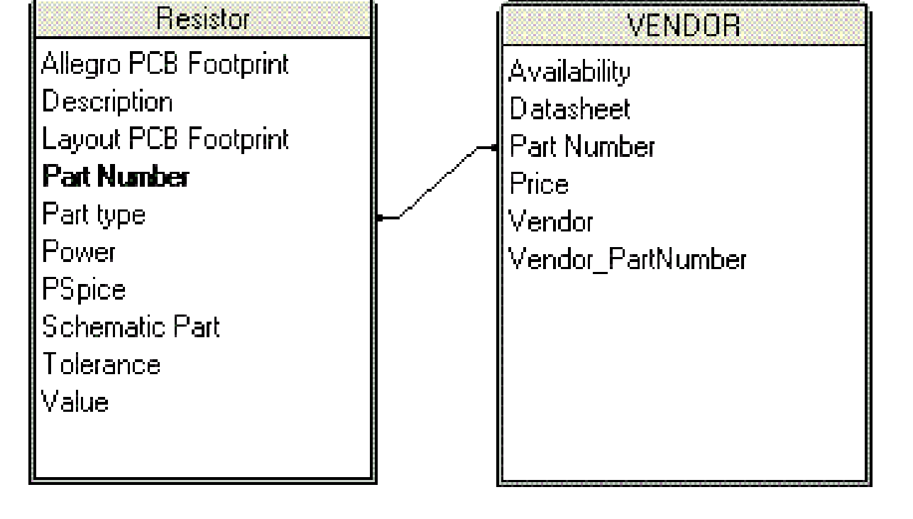
CIS allows you to create and use relational tables in your parts database. These tables must have a one-to-many relationship with your part information (primary) tables. For example, the database may contain a Vendor table with multiple vendor / manufacture part numbers for one company part number in your Resistor table. This structure allows you to query for data across the primary and relational tables.
It is not necessary for the parts database to contain relational tables. You can create and run CIS queries for parts from a flat table structure.
ERP or MRP Database Part Information Extraction
You can also extract information from an existing enterprise or manufacturing resource planning (ERP or MRP) database, to create a part database. Save the ERP or MRP database as an ASCII file, then use that file as your part database file or as a source for a true part database file (for example, an MS Access format file).
If your ERP database is ODBC compliant, you may not need to extract part information. Instead, you should be able to directly connect your preferred part database (PPD) to the ERP database–you should not have to set up and run regular batch routines to update the data in your PPD.
You may need to enhance the information in an ERP or MRP database, since it generally will not include everything required for schematic design. However, an ERP or MRP database usually contains a complete list of your company’s parts, part numbers, part descriptions, costs, quantities in stock, lead times, manufacturers, and alternate manufacturers.
Often, the data in an ERP or MRP database exists in a format that does not lend itself to ease of use. For example, the part value may be merged with the description, such as:
RES 1K 5% 1/4W
This makes searching for parts more difficult. If you can, split this information out in the ERP or MRP database into separate database properties, such as Part Type, Value, Tolerance, and Rating.
You can also contact the Cadence Methodology Services group for assistance in converting your data into a more convenient format.
To take advantage of updated information in an ERP or MRP database, you need to set up a means of extracting data on a regular basis and using it to update your part database. That way, your part database will include information that changes frequently, such as quantity in stock and lead time.
Extracting Properties from an Existing Design
You can create a part database by extracting part properties. This can be done using one of the following methods:
-
By exporting the part properties from the schematic and creating a part database manually.
In this method, only the properties present on the instance in schematic will be exported and can be used for creation of the new database. Hence, the new database may not have all the required part properties.
- From an existing Capture design using the CIS Bill of Materials (BOM) command.
Consider the following example for the second method:
- Open a new or existing schematic design in Capture CIS.
- Select Reports – CIS Bill of Materials – Standard.
The Standard Bill of Materials window opens. - Select properties from the Select Properties list and click the Add button.
- The Output Format list gets updated and it lists the number of properties that will be extracted to the bill of materials.
- To remove properties from the Output Format list, select the property in the Output Format list, and click the Remove button.
- Click OK.
CIS creates a file with the property information for all the parts in the design. - Select File – Save As to save the file in the desired format.
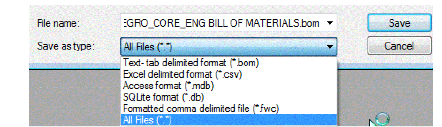
- Use this format to further import the extracted information into your database.
- Configure this saved database in your system to use it other Capture CIS designs.
Your database should have a unique part number for each part and no duplicate part entries. Although some database applications will not import more than one occurrence of a keyed property, you may need to eliminate duplicate part entries manually. To do this, sort the database by part number, then delete duplicate entries using your database or spreadsheet program.
Setting up the ODBC Data Source
Before you can set the CIS configuration, you must define the open database connectivity (ODBC) data source for your database. CIS interfaces to your part database using a defined ODBC data source name. A data source consists of a database filename and an associated ODBC driver with which to access it. If you are setting up a client-server database, the data source also references the database server. You define the data source name, assign the database file name, and specify the ODBC driver using the ODBC Windows control panel.
You must define the data source on each user’s system. When you do so, use the same data source name. This allows users to share the same configuration file.
If your workgroup is sharing a configuration file, make sure to write-protect the file.
To set the data source for the local database, do the following:
- From the Windows Start Menu, choose Control Panel.
- To run the 64-bit ODBC driver, do any one of the following:
- Choose System and Security – Administrative Tools – Data Source (ODBC) , if you have selected Category in the View by drop-down list.
- Choose Administrative Tools – Data Source (ODBC), if you have selected Large icons or Small icons in the View by drop-down list.
To run the 32-bit ODBC driver, run the odbcad32.exe application from the C:\windows\syswow64 directory path and follow the steps from step 3. - Click the Drivers tab.
Ensure that the driver appropriate to your database or spreadsheet is installed on your system. If the driver for your application is not present, you must install it. Check the CIS installation disk or contact the database or spreadsheet program supplier.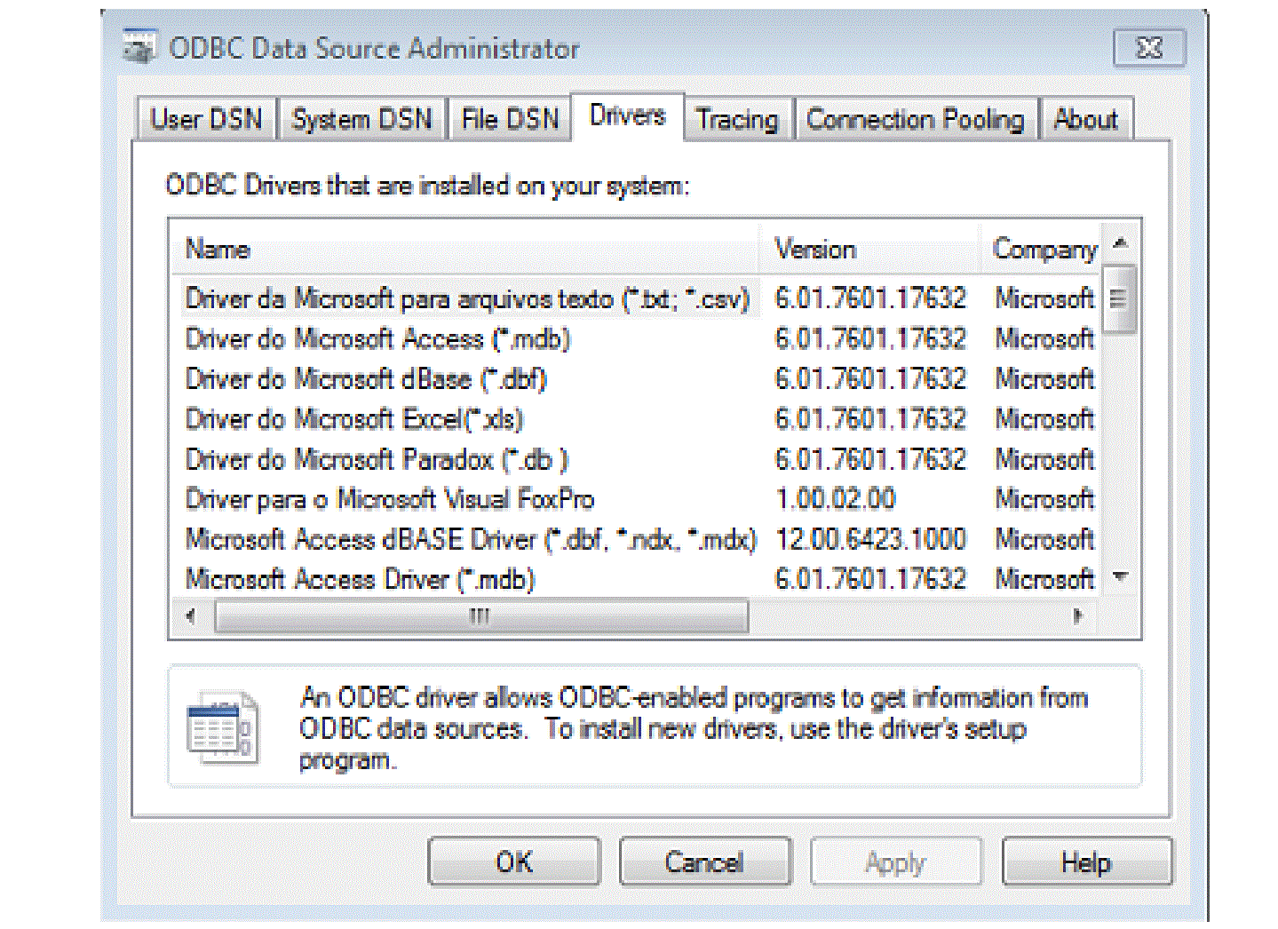
- Click the User DSN tab, and then choose the Add button. The Create New Data Source dialog box opens.
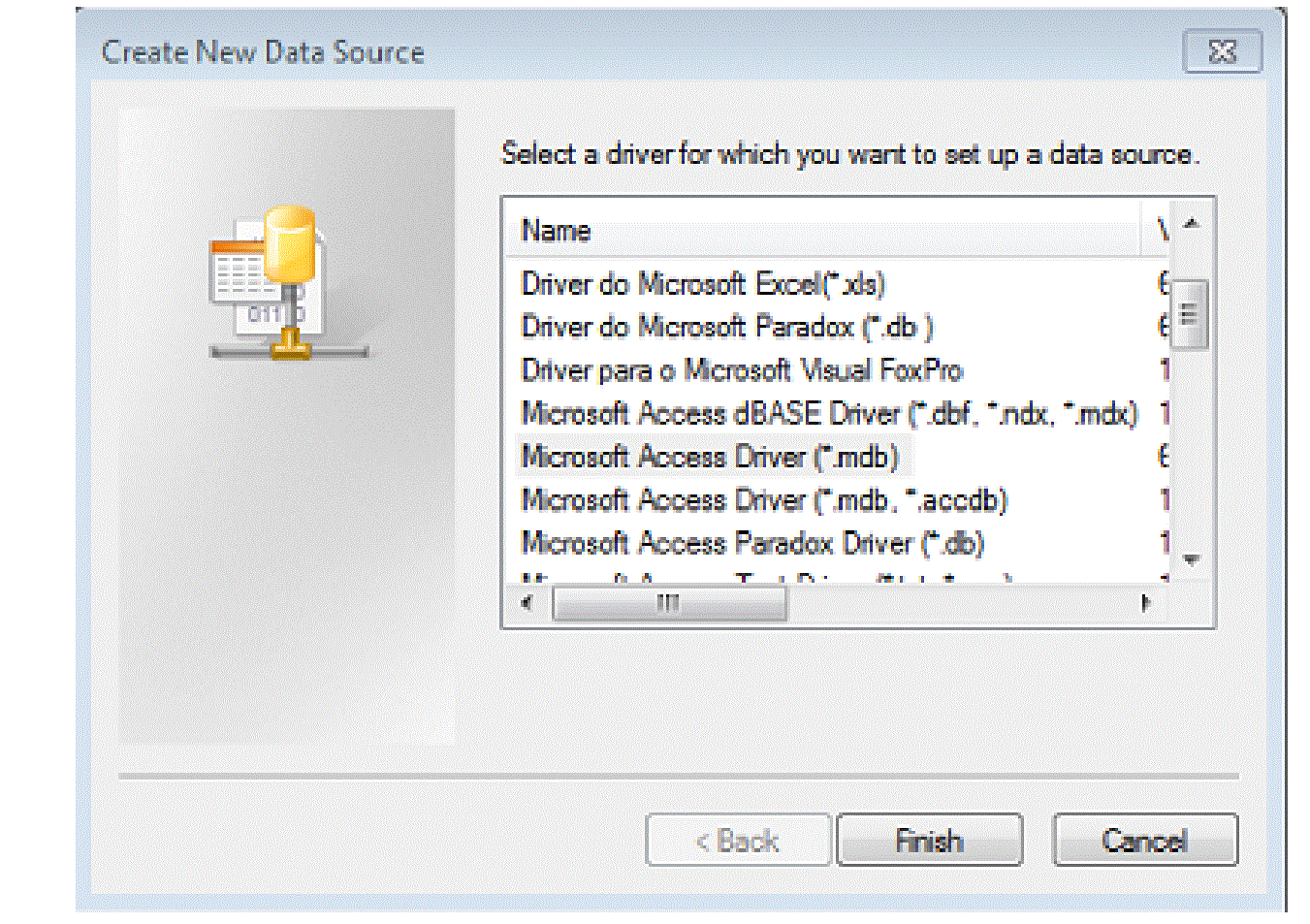 If you are using a Windows based operating system, click the System DSN tab to create new data sources. If you do not use the System DSN tab, users with different logins will not be able to use the ODBC source.
 - Choose the appropriate driver for your program (Microsoft Access, in this example), then click the Finish button.
In this example, the ODBC Microsoft Access Setup window opens.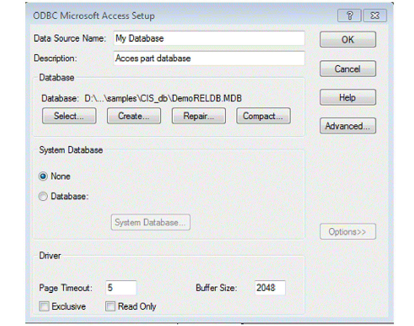
-
Assign a name for the data source. Specify a description for the data source name, if required.
Step 7 may be different depending on the type of program you used to create your database.
- Under Database, click the System Database button, and locate the database.
- Click the Options button, and clear the Read Only check box. By deselecting the Read Only check box, you can create new parts and add them to the database using CIS.
- Click OK to set the data source.
Creating a Configuration File
CIS requires a configuration (.DBC) file to make use of your part database. The configuration file:
- Identifies the ODBC data source to use as the part database and specifies the tables to use within that database.
- Identifies the part properties that are transferred to your design when you place or link a database part.
- Sets the visibility for each of the transferred properties.
- Contains the part type associations.
Keep the configuration (.DBC) file in a read-only directory that is accessible to all CIS users. You should make the directory read-only to prevent users from inadvertently changing the configuration.
You can create a configuration file using the following ways.
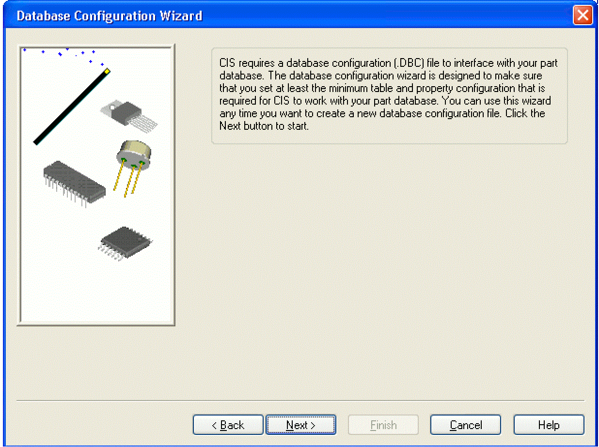
Using the Database Configuration Wizard
You can use the database configuration wizard each time you want to create a new database configuration file. The wizard is designed to make sure that you set at least the minimum table and property configuration that is required for CIS to work with your part database.
However, the wizard does not include all the options available to you, including options to optimize the performance of CIS and customize your CIS work environment. For this reason, when you have finished running the wizard, you should read through the last two parts.
You must set up a new ODBC data source before you can create a new configuration file.
Starting the Database Configuration Wizard
You can start the database configuration wizard anytime you want to create a new database configuration file.
To start the database configuration wizard, do the following:
- From the Capture’s Options menu, choose CIS Configuration. CIS displays the CIS Configuration File dialog box.
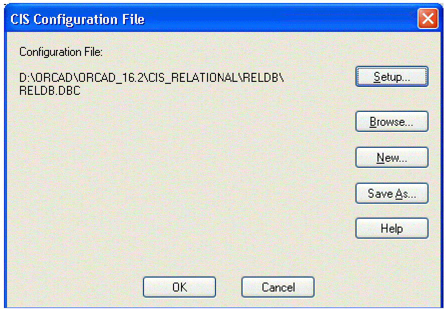
- Click the New button. CIS displays the Database Configuration Wizard.
- Follow the instructions in the wizard to create your database configuration file. If you need more information about any of the wizard steps, click the Help button.
- Click the Finish button. CIS displays the Configure Database dialog box and the wizard is complete.
- If you want to set other part database options, complete the steps.
- If you do not want to set any other part database or configuration options, click OK to save the new database configuration file.
Setting Other Part Database Options
You can set other part database options that are not available in the database configuration wizard, including:
- The part properties to be checked against the part database when you update the part status of a design. CIS sets which properties are checked by default but, if you have a special situation that requires different properties to be checked, you are allowed to change the defaults.
- The part tables that CIS searches when you are linking placed parts to database parts. This is useful when your database consists of several part tables that are organized by device type (for example, capacitors in one table, resistors in another, and so on). When you are linking database parts to placed parts, CIS uses allowed part reference prefixes to limit your search to the appropriate tables. The result is that your search takes less time.
To set other part database options, do the following:
- In the Configure Database dialog box, select the Part Database tab.
- In the Tables list, select the database table for which you want to set options.
- In Update Property column of the Configuration area, select the check box for each property that you want to be checked when you update the part status of your designs.
-
In the Allowed Part Reference Prefixes text box, type the part reference prefixes you want CIS to use to limit searches on the database table. For example, if a table contains only capacitors, you could enter C as the allowed part reference prefix. Then, when you choose the Link Database Part command, CIS searches that table only when the placed part you are linking has a part reference prefix of C.
If a part reference prefix is specified in the Allowed Part Reference Prefixes text box for all the tables, the following message is prompted on the screen after you click OK:
INFO(ORCIS-6235): All parts might not be accounted for. Do you want to continue?
Leave this box blank if you want the table to be searched regardless of the part reference prefix.
If you have defined part reference prefixes and you link a placed part in your design to a database part with the Preserve Reference Designator check box checked in the CIS Extended Linking dialog box, the reference designator of the placed part is retained and all the transferable properties of the database part are transferred to the placed part. Now, when you update the part status from the part manager (using Update All Part Status command), the part status column displays: Approved: Part not found. This is because CIS is unable to find the part (with matching part reference prefix and properties) in the database table. You may avoid this situation by changing the reference designator of the placed part to the one you defined in the Allowed Part Reference Prefix text box or delete the part reference prefix from the Allowed Part Reference Prefix text box.
Check the following:
- Repeat this procedure on each database table for which you want to set these options.
- If you do not want to set any other part database or configuration options, click OK to save the new database configuration file.
- If you want to set other configuration options, go to the next section.
Setup Options for Other Configuration
You can set other options in the database configuration that customize how CIS interacts with your part database and how you use CIS in your work environment. These options include the following tasks:
- Defining part reference associations to improve the speed and accuracy of the search for database parts to link to placed parts.
- Setting administrative preferences to customize some CIS features for your work environment.
- Setting relational database to set up the relational associations between the primary (part) tables and the relational table.
Creating a Configuration File Manually
You can create a configuration file using the manual procedure below. When you are finished creating the file, you will need to set the options for the file so that CIS knows how to handle your database table part properties.
To create a configuration file manually, do the following:
- Open a new or existing schematic design in Capture CIS.
-
From the Options menu, choose CIS Configuration. CIS displays the CIS Configuration File dialog box.
You must set up a new ODBC data source before you can create a new configuration file.
- Click the Setup button. CIS displays the Configure Database dialog box.

4. Click the Browse button. CIS displays the Browse Data Source dialog box.
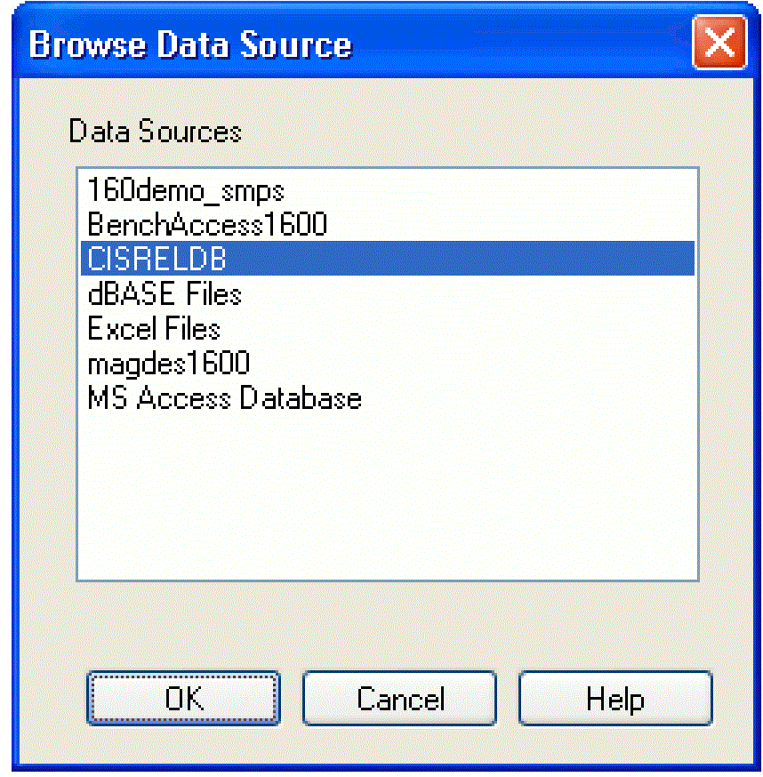
5. Select the data source name you defined for your ODBC driver, then click OK. The Configure Database dialog box lists the tables found in your data source.
6. Set the configuration file options as desired.
Editing a Configuration File
As you set up and work with CIS, you may discover performance issues or elements of the CIS work environment that are not optimal for your workgroup. This section describes in detail all the configuration options that are available and how to set them optimally for your situation. It includes the following tasks.
Setting Database Table Property Options
Once you have created a database configuration file, you need to set the options for the file so that CIS knows how to handle your database table part properties.
To set database table property options, do the following:
- Open a new or existing schematic design in Capture.
- From the Options menu, choose CIS Configuration. CIS displays the CIS Configuration File dialog box.
- Choose a configuration file to edit by doing one of the following:
- To edit the current configuration file, click the Setup button.
- To edit a different configuration file, click the Browse button, locate and open the file, then click the Setup button.
CIS displays the Configure Database dialog box.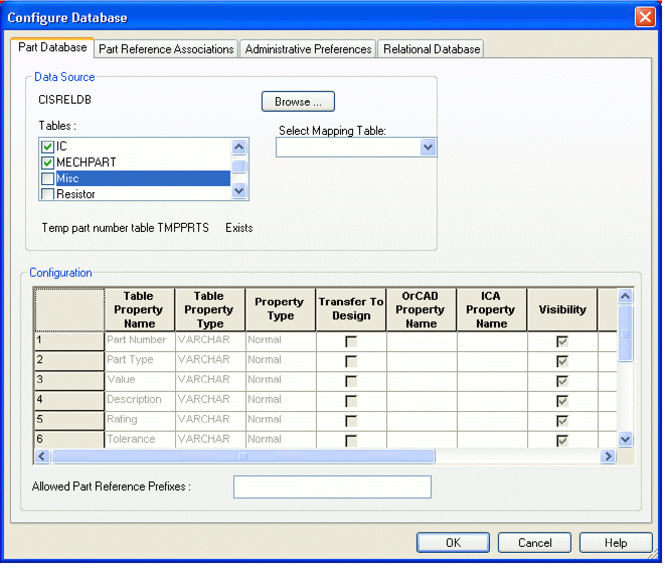
-
If you want to choose a new data source for your configuration, do the following:
If you choose a new data source name, all of the settings made with the previously selected data source will be lost for the current configuration (.DBC) file. If you want to keep the settings in the current .DBC file, use the database configuration wizard to create a new configuration file instead.
- Click the Browse button. CIS displays the Browse Data Source dialog box.
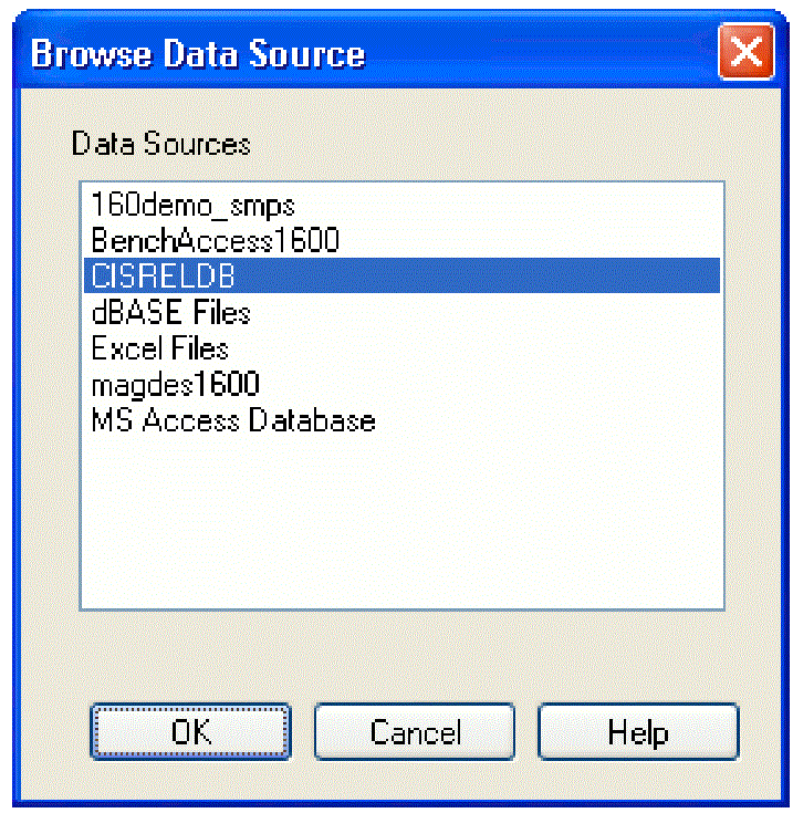
- Select the data source name you defined for your ODBC driver, then click OK. The Configure Database dialog box lists the tables found in your data source.
- Click the Browse button. CIS displays the Browse Data Source dialog box.
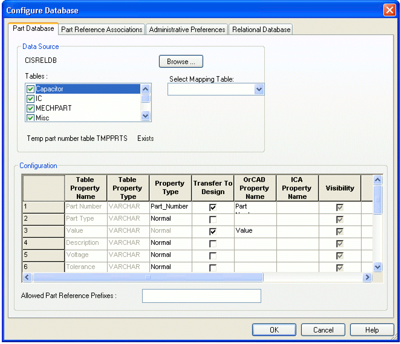
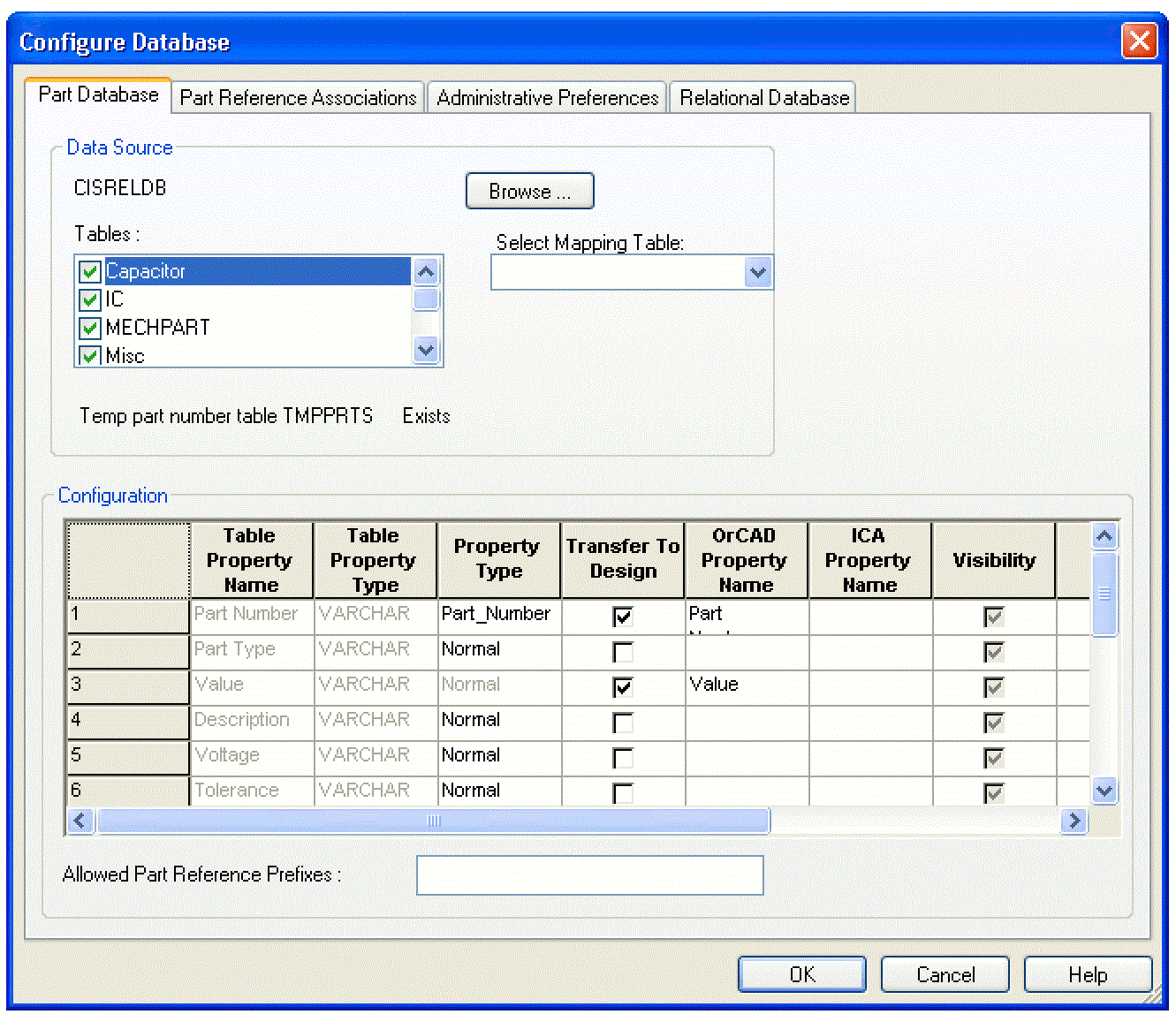
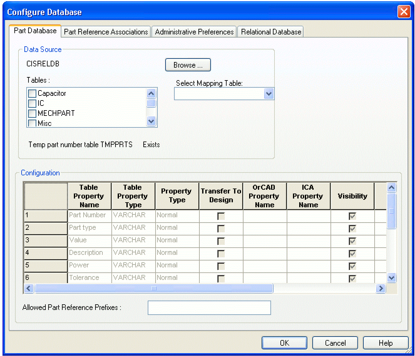
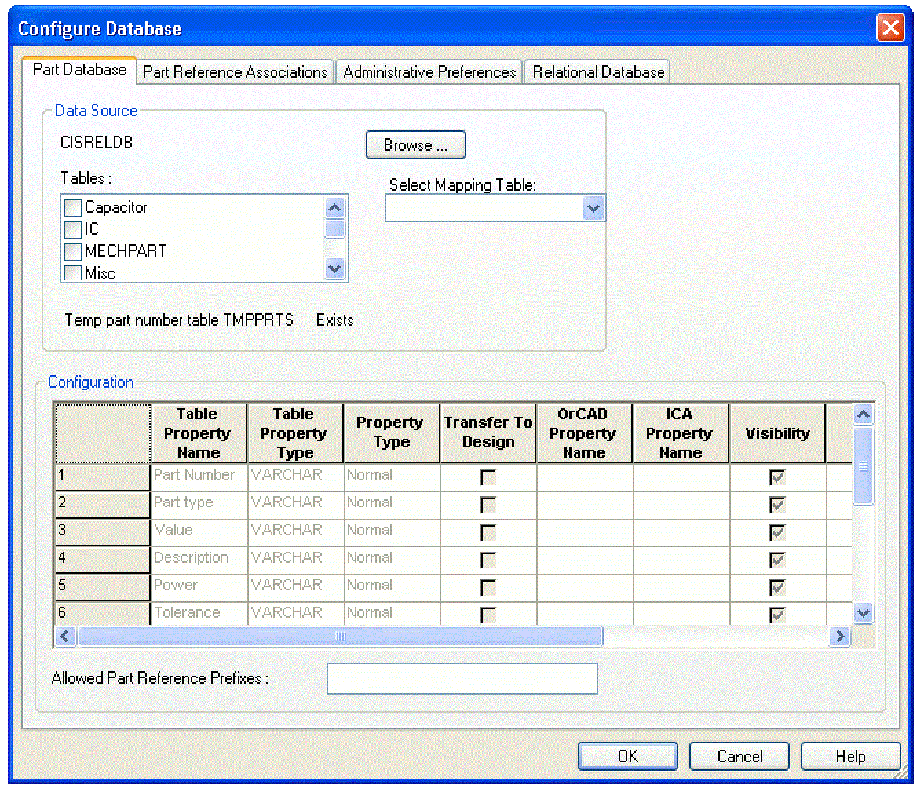
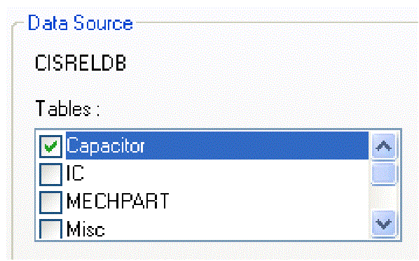
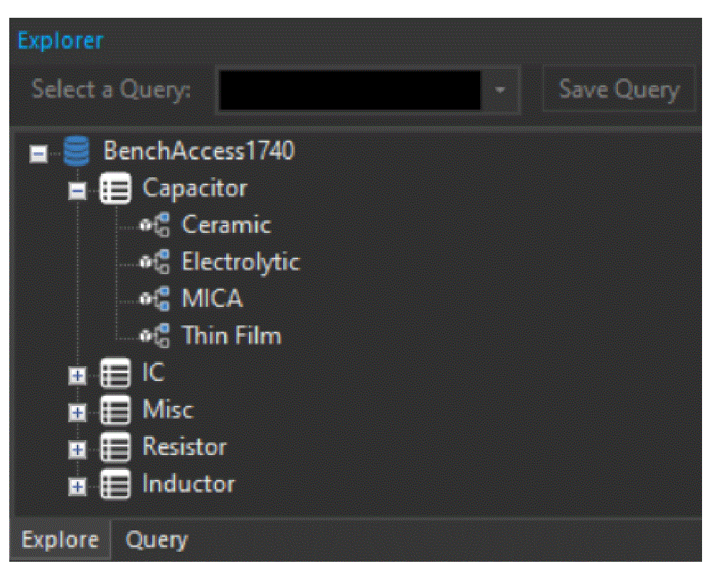
- If you want to configure table properties, select the table that contains the properties. In the graphic below, the Capacitor table is selected.
When you select a table, the Configuration area lists the properties it contains. Each row represents a part property, and each property has the following characteristics:
Table Property Name
This is the name of the property as it is defined in the part database.
Table Property Type
This is the data type for the property. Most properties are type Text, but there may be other data types.
Property Type
The Property Type determines how CIS interprets the property. Your database must include a property of type Part_Number in every table.
Set the following property types:
- The Part_Type type for the database property that defines the part type. (This defines the field for folder view in CIS explorer.)
- The Schematic_Part type for the database property that contains the schematic part (symbol) name.
- The PCB_Footprint type for the database property that contains your Layout footprint name. If you want the database to include footprints not generated by OrCAD X Layout, set the property type to Normal. This prevents the footprint viewer from trying to interpret them.
Visibility
This sets the default visibility of the property when it is copied to the placed part. There are four visibility modes:
| Visibility mode | Description |
|
|
Visible CIS displays the property with the part on the schematic page. |
|
|
Invisible CIS does not display the property with the part on the schematic page. |
|
|
No Change CIS does not modify the property visibility. If the property does not exist, it is set to invisible. You can override the default visibility for specific parts when you place or link database parts. Cells that you cannot change are shown with a light gray background in this column. |
|
|
Non-adjustable CIS does not allow this property to be set as visible on schematic pages. |
Key
This sets the property as a key during the initial part search. The key is used when you are linking a database part to a previously placed part. Normally, you set only the Value property as a key so that, when you want to link a part, CIS searches the part database for parts with a specific value. If you don’t have a Value property in your database, do not set a key.
Browsable
This sets browse capability for the property. It allows you to put references to datasheets, drawings, and documents in your part database. For example, you can reference Adobe Acrobat (.PDF) files, Microsoft Word (.DOC) files, and even worldwide web addresses (URLs). You can then view these items online in CIS when browsing the part database. They are also browsable when you are viewing standard CIS bills of materials.
You can browse any file type, such as .PDF, .DOC, or .HTML, from the CIS explorer window when you have a browser installed on your system that can read the file and can be automatically launched. CIS automatically locates and reads all viewable files that are stored in the same directory as your .DBC file.
You can set parameters for viewing a specified document in the CAPTURE.INI file. For more information, see the CIS online help.
Update Part Property
Select this if you want the value of this property for placed parts to be checked against the database part’s value when you update the part status of your design.
-
(Optional) Type the part reference prefixes in the Allowed Part Reference Prefixes text box.
This is useful when your database consists of several part tables that are organized by device type (for example, capacitors in one table, resistors in another, and so on). When you are linking database parts to placed parts, CIS uses allowed part reference prefixes to limit your search to the appropriate tables. The result is that your search takes less time.
For example, if a table contains only capacitors, you could enter C as the allowed part reference prefix. Then, when you choose the Link Database Part command, CIS searches that table only when the placed part you are linking has a part reference prefix of C.If a part reference prefix is specified in the Allowed Part Reference Prefixes text box for all the tables, the following message is prompted on the screen after you click OK:
INFO(ORCIS-6235): All parts might not be accounted for. Do you want to continue?
Leave this box blank if you want the table to be searched regardless of the part reference prefix.
- Repeat steps step 4 for each table in the database.
- When you are finished configuring table properties, click OK or choose another tab to continue configuring your database.
Defining Part Reference Associations
Part reference associations are used to improve the speed and accuracy of the search for database parts to link to placed parts. You create associations between a particular part type and the prefixes in the part database for that part type. For example, you can create a part reference association for resistors such that all resistors in the part database use the R prefix.
Defining part reference associations only improves part search speeds for true databases (for example, Microsoft Access)—there is no speed improvement from setting up associations if you are using a spreadsheet or a text file for your database.
You must create a configuration file for your database before you can define its part reference associations.
Once you’ve defined part reference associations for your database, when you choose the Link Database Part command, CIS displays database parts of the appropriate type. Without defined part reference associations, CIS displays all parts in the database that match the keyed property value, regardless of the part type. By defining an appropriate reference association, you can limit the number of parts that CIS displays.
Defining part reference associations is optional. You can define associations later if you need to improve the search performance during database part linking.
Example: If you select an inductor, L1, on the schematic page with a value of 100uH, then choose the Link Database Part command, CIS displays all parts in the database having a value of 100 x 10-6. This may include capacitors, inductors, or other parts with a similar value.
By defining a reference association between inductors and the L prefix, you can limit the parts that CIS displays to inductors only.
When you define part reference associations for your part database, keep the following points in mind:
- Part reference associations apply to all database tables.
- The Part Type Property Contents value in the dialog box is case-sensitive.
- You can associate one prefix with several different part types.
- An association applies to its level in the part type hierarchy and all lower levels.
- A part reference prefix without a defined part type association can be matched to any part type in the database.
- If a particular part in the database does not have its Part Type property contents defined, that part will be matched only to part reference prefixes with no defined part type associations.
Example: An association between the part reference prefix C and the part type Capacitor applies to part types of Capacitor, Capacitor\Electrolytic, and Capacitor\Ceramic\Fixed. Note that a part reference prefix associated with the part type Capacitor\Ceramic does not apply to part types of Capacitor or Capacitor\Electrolytic.
To define part reference associations, do the following:
- In your local preferred parts database, make sure that the Part Type property field is indexed.
- If you are not already in the Configure Database dialog box, do the following:
- Open a new or existing schematic design in Capture.
- From the Options menu, choose CIS Configuration. CIS displays the CIS Configuration File dialog box.
- If necessary, click Browse to locate the database configuration file you want to setup.
- Click Setup. CIS displays the Configure Database dialog box.
You can add icons for custom part references that will automatically display in the Part Reference column of the part manager window. Add your custom icons to the standard icons used for the Part Reference column located in the directory: \TOOLS\CAPTURE\VENDOR
Each icon’s filename corresponds to a part reference prefix (for example, the icon for the part reference prefix R is stored in R.BMP).
You can use a bitmap editor (such as Microsoft Paint) to modify the bitmaps, but be careful not to change the image size.
- In the Configure Database dialog box, choose the Part Reference Associations tab.

-
Enter a part type in the Part Type Property Contents column and a corresponding part reference prefix (or set of prefixes) for that part type in the Applicable Part Reference Prefixes column. Separate prefix entries with commas.
Part prefixes need not be unique to a particular part type. That is, you can make an association between one prefix and several different part types.
Use the Delete keyboard key to delete a row containing the part type and the corresponding part reference prefix.
- Click OK or choose another tab to continue configuring your database.
Setting Administrative Preferences
Administrative preferences allow you to customize some CIS features for your work environment.
To set administrative preferences, do the following:
- If you are not already in the Configure Database dialog box, do the following:
- Open a new or existing schematic design in Capture.
- From the Options menu, choose CIS Configuration. CIS displays the CIS Configuration File dialog box.
- If necessary, click Browse to locate the database configuration file you want to setup.
- Click Setup. CIS displays the Configure Database dialog box.
- In the Configure Database dialog box, choose the Administrative Preferences tab.
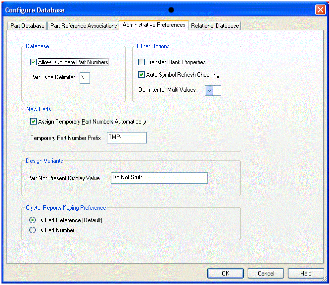
-
Select the Allow Duplicate Part Numbers check box to allow the same part number to appear more than once in the database.
If you want a database part to work with two or more different layout footprints, you can enter multiple PCB footprint names in your part database.
- In the Part Type Delimiter text box, type the character that indicates a hierarchical level within a path in the database. Normally, the delimiter is a backslash (\) character. For example, The database could have part types Capacitor\Electrolytic and Capacitor\Ceramic.
- Select the Transfer Blank Properties check box to create a property on the placed part even if the database part property does not have a specific value. This is useful if all your database parts are in a single table since, in that case, you will have properties in the table which are not relevant to certain types of parts. For example: Speed Grade does not apply to resistors.
- Select the Auto Symbol Refresh Checking check box to enable CIS to automatically detect if symbols or footprints were updated in the configured libraries. If any changes are detected, the Refresh Symbols from Lib command in the Update menu in CIS explorer and its corresponding icon on the toolbar are enabled. This indicates that you have to refresh the symbol or footprint information in CIS explorer.
If you do not select this check box, the Refresh Symbols from Lib command in the Update menu in CIS explorer and its corresponding icon on the toolbar will always be enabled. - If you want to use a character other than a comma to separate multiple field values in your database, choose another character from the Delimiters for Multi-Values list.
Select the Assign Temporary Part Numbers Automatically check box so that CIS will create and track temporary part numbers for you. That way when you create a new part, CIS automatically assigns a temporary part number to that part and enters the part number into the part record in the database as well as in a special table named TMPPRTS.
CIS automatically creates the TMPPRTS table. Do not remove, rename, or modify the structure of this table or temporary part number tracking will not operate properly. Also, never remove temporary part records, even after you have assigned them approved part numbers. If you do, designs that have not yet been updated with the new part numbers will have to be updated manually.
To promote a temporary part to an approved part, do the following:
- Using your database application, enter the approved part number RELPRTNO field in the TMPPRTS table.
- Replace the temporary part number with the approved part number in the part table.
- Open Part Manager.
- From the Tools menu choose Update All Part Status.
All temporary parts will be promoted to approved parts. Also, the part numbers will be updated part number values from the RELPRTNO field in the TMPPRTS table.
- In the Temporary Part Number Prefix text box, enter the prefix to use for temporary part numbers. CIS automatically increments the temporary part number each time you create a new part. The temporary part number is then appended to this supplied prefix. our workgroup is using a shared, read-only database configuration file, all users must use the same temporary part prefix.
- In the Part Not Present Display Value text box, enter the text description that you want CIS to use for variant parts set to Not Present. The property is displayed in the following locations
- Part Number and Value fields in the part manager
- Design variant columns in variant reports
- Variant parts on schematic page previews and printouts.
If your workgroup is using a shared, read-only database configuration file, all users must use the same temporary part prefix.
The Part Not Present Display Value does not display in Capture’s schematic page editor. This property also cannot be repositioned or edited in the schematic page editor. For this reason, you will have to print preview or print a schematic page to make sure that the value you assign the property does not overlap another part or property display.
- In the Crystal Reports Keying Preference section, choose to sort by part reference or by part number. The default is to sort by part reference
- Click OK or choose another tab to continue configuring your database.
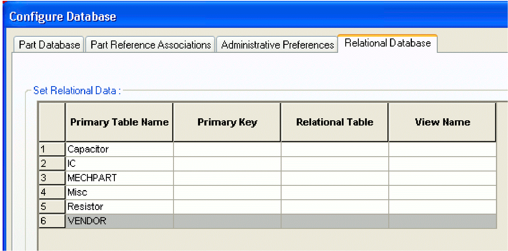
Setting Relational Database Preferences
Capture CIS allows you to create and use relational databases. You can define the primary - foreign key relationship between the parts (primary) tables and related tables in the database.
In the Relational Database tab, you define the relationship between the part (primary) and relational tables in the database.
The Set Relational Data grid contains the following fields:
Primary Table Name: Use this list to define the part (primary) tables in your relational database. This is the only read-only field in the grid.
Primary Key: Use this list to define the primary key that you want to use to form the relationship with the relational table
Relational Table: Use this list to specify a relational table that has a primary - foreign key relationship with the selected primary table.
View Name: Use this text Field to define a friendly name for the view that will display when a user selects the primary table to create a relational query.
To define the relational data, do the following:
First, ensure you are in the Relational Database tab of the Configure Database dialog box. Go to a row that contains a primary table (for example, Capacitor as displayed in the following figure).
-
Select the Primary Key field drop down list.
This list displays all the fields in the primary key table.If the specified ODBC driver provides support for retrieving the primary key, this will be displayed by default in this field for the corresponding primary table.
- Select the field to use in your relation.
- Select the Relational Table field drop-down list.
This displays the list of tables in the database that have a primary - foreign key relationship with the corresponding primary table. - Select the table to form the relationship with the primary table.
- In the View Name field, define a friendly name for the view that will display when a user selects the primary table to create a relational query.
Repeat Steps 1 through 4 for every table in Primary table list that is to be defined as a primary table in CIS and you want to create a relationship with a relational table. - Click OK or choose another tab to continue configuring your database.
To save the configuration file, do the following:
- (Optional) In the CIS Configuration File dialog box, choose Save As to save the configuration for future use.
- Choose OK to set the configuration for the current session and close the CIS Configuration File dialog box.
View the next document: 04 - CIS User Interface
If you have any questions or comments about the OrCAD X platform, click on the link below.
Contact Us