Isolated Power Supply Design Guidelines
Key Takeaways
-
Choose transformers based on isolation voltage and switching frequency, while minimizing leakage inductance.
-
Keep power connections short, maintain creepage/clearance, and separate primary/secondary grounds.
-
Use input/output filtering, shielding, and snubber circuits to minimize emissions.
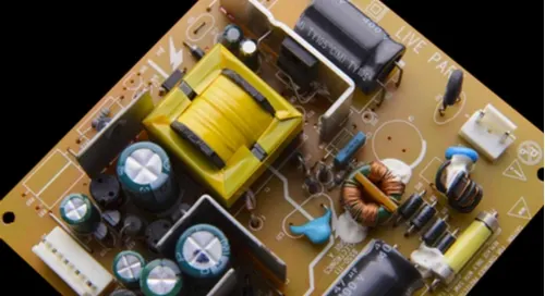
The use of a transformer in an isolated power supply will protect users from electrical shock.
When designing a circuit board, components require power at specific voltages to function. Usually, one or more power supplies are designed onto the board to fill this need. Different types and configurations of power supplies exist —read on as we delve into isolated power supply design.
Isolated Power Supply Design Guidelines
|
Category |
Design Tips |
|
Transformer Selection |
- Ensure the transformer is rated for the required isolation voltage. |
|
PCB Layout Considerations |
- Place components to keep your power connections as short and direct as possible. |
|
EMI/EMC Considerations |
- Implement proper input and output filtering to reduce conducted emissions as needed. |
|
Feedback and Control |
- Use transformers or opto-isolators for feedback across isolation barriers. |
|
Safety Considerations |
- Routing should be as short and direct as possible. Ensure trace widths are wide enough to handle the current load. |
|
Thermal Management |
- Ensure adequate cooling for power components like MOSFETs, diodes, and transformers. |
|
Grounding and Isolation Barriers |
- Keep primary and secondary grounds separate. |
|
Power Stage Design |
- Optimize switch timing to reduce losses. |
|
Protection Mechanisms |
- Implement over-current, over-voltage, and short-circuit protection. |
|
Common-Mode Noise Reduction |
- Use balanced layouts to minimize common-mode currents. |
|
Capacitive and Inductive Coupling |
- Minimize capacitive coupling by increasing physical separation. |
|
Design for Manufacturability |
- Ensure PCB can be manufactured reliably with chosen design features. |
Why Use an Isolated Power Supply?
There are two types of power supplies that can be designed into a circuit board; isolated and non-isolated. Although isolation can refer to separating the power supply parts from the rest of the design on the PCB, it usually refers to isolation between the inputs and outputs of the power supply itself. This isolation is typically done with a transformer, which by its design provides a barrier that dangerous voltages spikes or changes can’t cross to invade the rest of the board circuitry A non-isolated power supply on the other hand relies on integrated circuits for separation, which don’t provide the same level of protection.
The separation that an isolated power supply affords in turn provides safety to the user. For devices that are stepping down high voltages, such as medical equipment, you don’t want any chance that a problem could shoot that high voltage straight into the user. On the other hand, the components of an isolated power supply, such as the transformer, take up extra space and add cost. If the device doesn’t have the system or safety standards that require an isolated power supply, they may be better off without it. Non-isolated power supplies are usually much more efficient than isolated supplies, and will sometimes even be used downstream of an isolated supply in a device.
Therefore, isolated power supplies will be used in applications that must meet safety requirements. Non-isolated supplies will be used only in applications where the entire device is enclosed for user safety, such as wireless smart-home IoT devices.
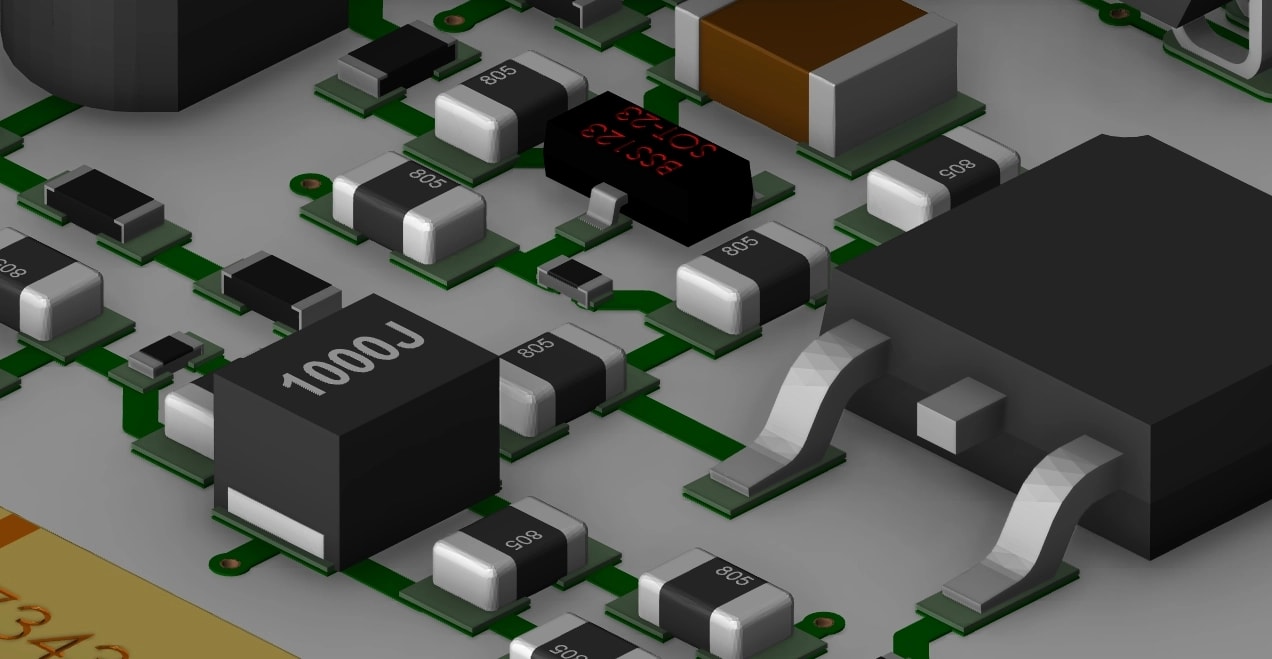
The right PCB design tools will help to place and work with the components in your design.
Stackup Design for Isolated Power Supplies
When you are laying out an isolated power supply on your printed circuit board, you are going to have to accept the fact that you are going to be working with some larger components. Depending on the needs of the design, those transformers can get rather large, and could throw your placement strategy out the window.
Plan ahead for the PCB layer stackup for your isolated power supply design. You will want to make sure that in multi-layer board configurations you have either a power or a ground layer between the outer layer of the board where the power supply components are, and the inner layers where sensitive routing may be passing through.
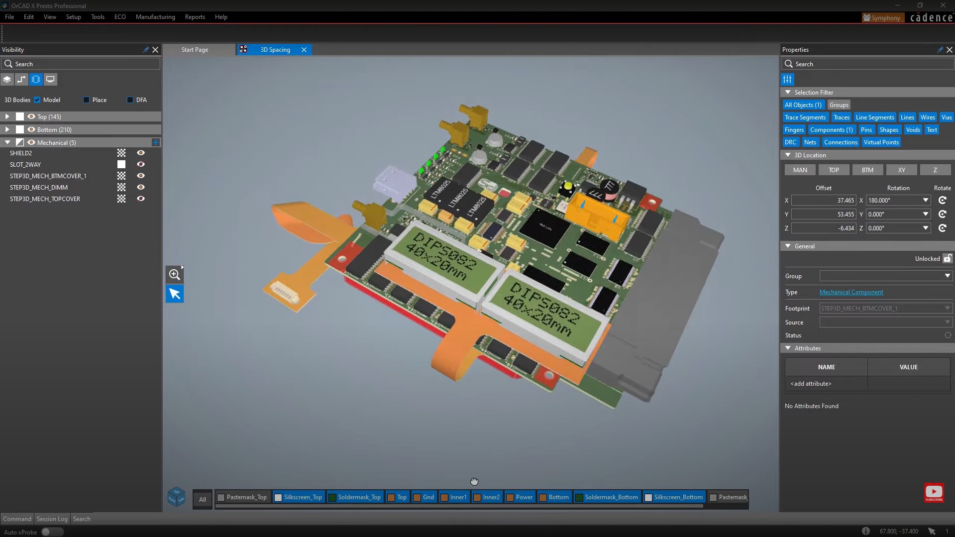
OrCAD X features a 3D Engine that aids in resolving 3D issues —that may be caused by a bulky transformer, for example.
OrCAD X For Isolated Power Supply Design
There’s a lot to consider when designing a power supply; different component clearances, trace widths, and ground plane connections are just the start. In order to manage all of these requirements, you need a versatile design tool that can be configured for the greatest amount of control.
|
Feature |
Description |
Benefits for Isolated Power Supply Design |
|
Design Rules and Constraints |
OrCAD X allows users to define specific rules for power supply components such as transformers, ground planes, trace widths, and clearances before starting the design. |
Ensures compliance with necessary electrical and mechanical constraints for large components like transformers, reducing errors during design. |
|
3D Layout and Clearance Check |
Interactive 3D viewing to detect clearance issues, especially for larger components like transformers, allowing real-time adjustments. |
Helps prevent mechanical issues such as transformer size misfit, ensuring proper placement for larger power supply components. |
|
Stackup Management |
OrCAD X provides advanced stackup configuration, including power or ground layers between signal layers for isolating power supply noise. |
Provides better noise isolation for sensitive circuits by managing layer configurations and adding specific ground or power layers. |
|
Thermal Analysis |
Built-in thermal analysis features help to assess and manage heat dissipation, especially under high loads common in power supply designs. |
Helps avoid overheating issues by identifying hot spots and optimizing placement of thermal vias or additional heat sinks. |
|
Ground Plane Management |
The ability to create separate power and signal ground planes, connecting them at a single point to reduce noise and interference. |
Reduces noise in the circuit by isolating power supply noise from signal paths, improving overall circuit performance and reliability. |
|
DRC for Power Supply Components |
OrCAD X allows setting component-specific clearances and trace width rules for large components like transformers, ensuring that placement and routing meet required electrical and mechanical clearances. |
Minimizes design errors related to clearances and trace widths, particularly for components such as transformers in isolated power supply designs. |
|
Via and Trace Management |
Provides detailed management for vias and traces, including wide traces for power supplies and thermal vias under hot components. |
Ensures that power traces can handle the required current loads and that heat is dissipated effectively. |
|
ECAD-MCAD Integration |
3D ECAD-MCAD integration for rigid-flex and power supplies to detect assembly issues and optimize designs in tight enclosures. |
Reduces errors in assembling power supply components into the final product, minimizing board re-spins. |
|
Impedance and SI Analysis |
Signal integrity and impedance analysis capabilities to ensure proper electrical performance of the power supply and connected components. |
Prevents issues such as impedance mismatch, improving signal quality in high-speed designs incorporating isolated power supplies. |
|
DFM Checks |
OrCAD X includes design-for-manufacturing (DFM) checks that ensure designs meet fabrication and assembly standards for power supplies. |
Reduces the risk of manufacturing defects in isolated power supplies by ensuring proper clearances, spacing, and layer configuration according to IPC standards. |
To help you with the design of your isolated power supply, use as much of the design rules and constraints in your CAD system as possible. Create power supply component classes so that you can set separate clearances for placement. In the same way, create as many individual net rules and net class rules to control all of the trace widths that you need. By setting these up before you start, you won't have to worry about fighting the online DRC’s while you are designing your power supply.
Another useful feature is the ability to view and check your power supply layout in 3D. This will tell you right off the bat about any clearance violation that you may have. Since your transformers and other power components are taller and larger than the other parts on your board, you may encounter problems that you normally don’t run across. The last thing that you want to find out during prototyping is that your transformer is busting through the device enclosure because it was in the wrong location.
An isolated power supply design requires careful attention to transformer selection, PCB layout, EMI management, and safety considerations. With OrCAD X, you can streamline your design process by applying custom design rules, performing real-time 3D clearance checks, and managing complex stackups for noise isolation. Learn more about how Cadence's PCB Design and Analysis Software and OrCAD X can help you create efficient and safe isolated power supplies.
Leading electronics providers rely on Cadence products to optimize power, space, and energy needs for a wide variety of market applications. To learn more about our innovative solutions, talk to our team of experts or subscribe to our YouTube channel.