05 - Working with Constraint Objects
This section explains some functions related to constraint objects in Constraint Manager:
- Managing XNets
- Performing Signal Analysis in Constraint Manager-Enabled Design
- Working with Electrical CSets
Managing XNets
When you enable Constrain Manager in a design in which a net traverses a passive, discrete device (resistor, inductor, or capacitor), XNets are automatically created.
In the Constrain Manager interface, such objects are specified as XNet in the Type column.
Creating XNets
To create an XNet, do the following:
- Open the required design in Capture.
- Enable Constrain Manager for this design. The Constraint Manager window opens.
- As an example:
- From the left pane, choose Net – Routing – Wiring.
- Check that the value corresponding to
SI[15]in the Type column is Net.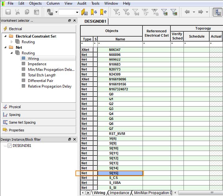
- Add a resistor to
SI[15].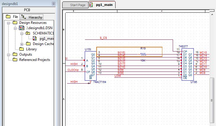
- Check that when you add a resistor, Net changes to
XNetin the Type column as highlighted in the following screen shot.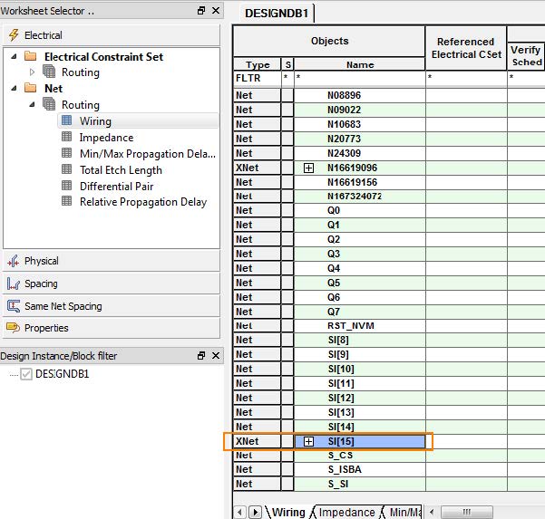
Creating an XNet using Non-Discrete Components
In case of non-discrete components, to convert a Net into XNet, do the following:
- Open the required design in Capture.
- Enable Constrain Manager for this design.
- Select the pins through which an XNet connection needs to be created.
- Right-click the pin set and select Edit Properties.
- Click New Property.
- Specify the XNET_PINS property to the selected pin set.
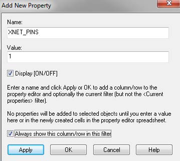
The applied property will be attached to one of the pin pairs.
You must apply the XNET_PINS property for each net that needs to be converted. - Click Apply.
You can see that the type has changed from Net toXNetin Constraint Manager.
Note: In Constraint Manager, the Xnet members are listed in alphabetical order and not based on the sequence of connectivity.
Removing an XNet
To remove an XNet, do the following:
- Enable the required design for Constraint Manager.
- Select a discrete component in an XNet.
The XNet highlighted in the following example will be removed.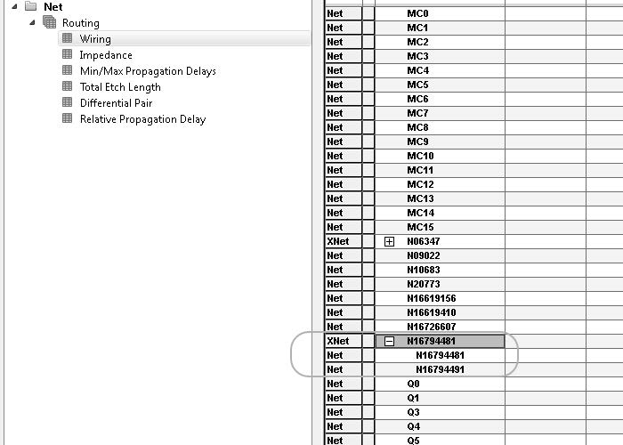
- Right-click the discrete component and select Edit Properties.
- Click New Property.
The Add New Property window opens. - Set the
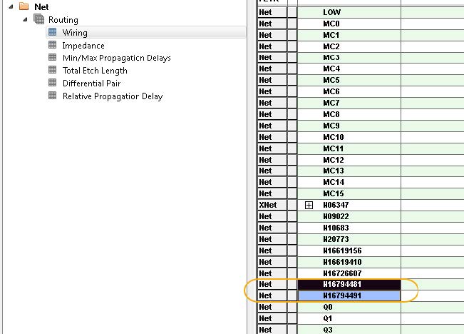
NO_XNET_CONNECTIONproperty toYES.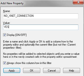
You can see that the Type has changed fromXNetto Net in the Constraint Manager UI.
Performing Signal Analysis in Constraint Manager-Enabled Design
You can view the topology of the signal flow and also assign constraints, such as propagation delay and relative propagation delay in the schematic and manage them using the Constraint Manager UI.
To view the topology and assign constraints, do the following:
- Open the required design in Capture.
- Enable Constrain Manager on this design. The Constraint Manager window opens.
- As an example:
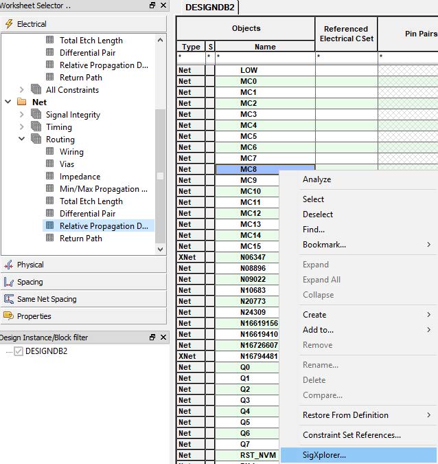
- From the left pane, choose Net – Routing – Relative Propagation Delay.
- Select a net, MC8.
- Right-click MC8 and select SigXplorer.
- Select a license with SI capabilities.
The SigXplorer OrCAD PCB SI window opens. - Choose Setup – Constraints.
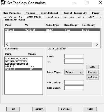
The Set Topology Constraints window opens.
- As an example, in the Set Topology Constraints window:
- Click the Prop Delay tab.
- Select the output and input pins.
- Specify the min delay as
9 nsand max delay as15 ns. - Click Add.
- A new rule is added in the Existing Rules section.
- Click Apply and then OK.
- Select File – Update Constraint Manager.
A message appears to confirm if the net can reference the Electrical Constraint Set. - Click Yes.
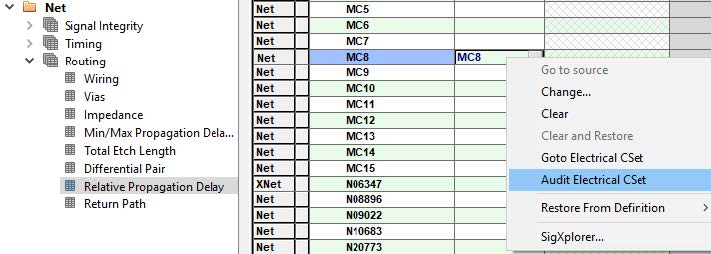
This constraint is now seen in the Constraint Manager window.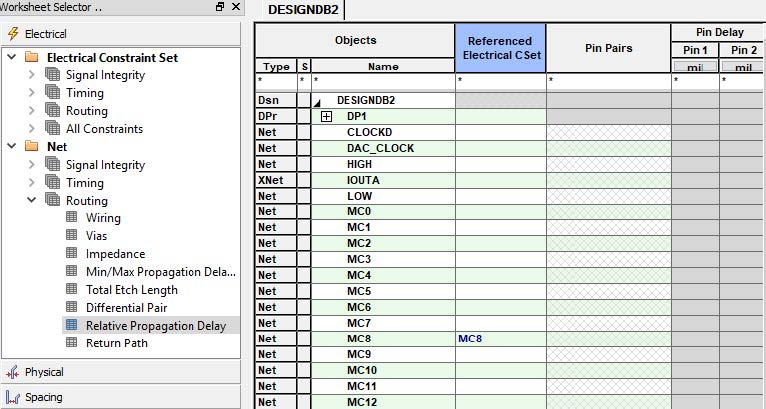
- Right-click this Electrical Constraint Set (Electrical CSet) to view the operations you can perform on it.
- Select Net – Routing – Min/Max Propagation Delay, you can view the pin pair that is created.
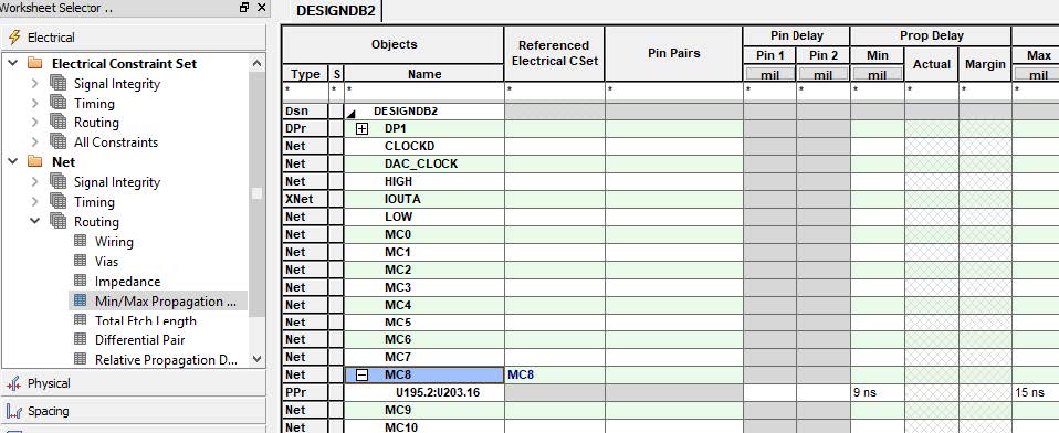
If the referenced Electrical CSet does not show the pin pair information, then Electrical CSet Apply feature will work with limitations. You need to upgrade to a higher license for this feature to function correctly.
Working with Electrical CSets
In Constraint Manager, you can define constraints on design objects using a Constraint Set (CSet). A CSet is a named and reusable collection of constraint values. CSet can then be assigned to a net in any of the Net worksheets.
To assign an Electrical CSet to a net, do the following:
- In a Constraint Manager-enabled design, open Constraint Manager.
- In the left pane, select Electrical Constraint Set – Routing – Total Etch Length.
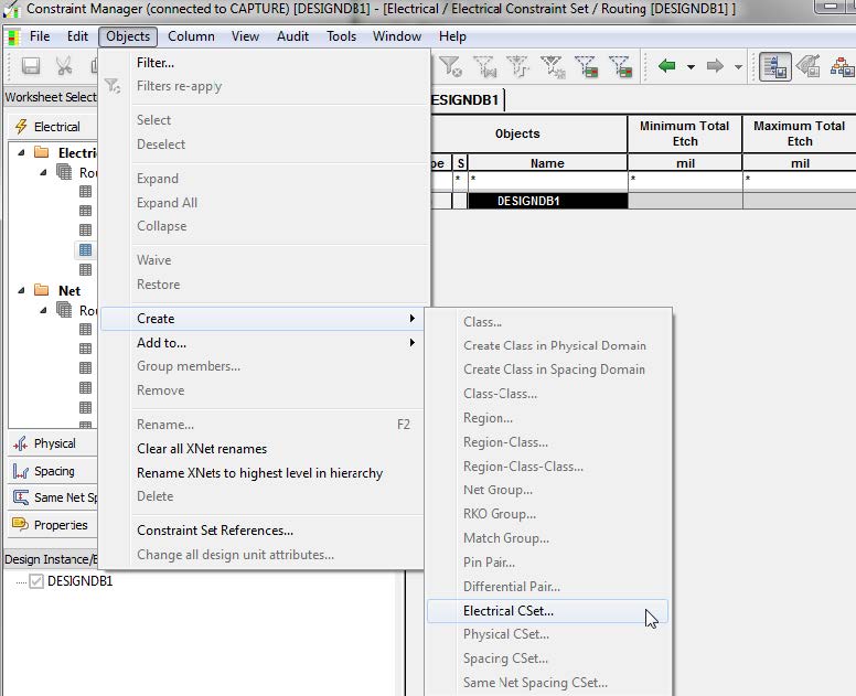
- Choose Objects – Create – Electrical CSet.
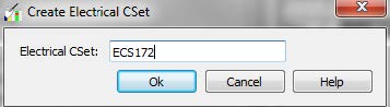
- Specify the name of the Electrical CSet.
- Specify the minimum and maximum total etch length for this ECSet.
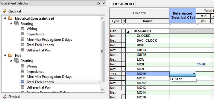
- Select Net – Routing – Total Etch Length.
- Select the nets corresponding to which you want to assign a ECSet under the Referenced Electrical CSet column.
View the next document: 06 - Modes for Processing Constraints: Overwrite and Changes Only.
If you have any questions or comments about the OrCAD X platform, click on the link below.
Contact Us