02 - Migrating Constraints
You can enable Constraint Manager on a Capture design with migration of constraints using any one of the following two options:
- Migrate constraints from schematic design. This can be a schematic:
- with constraints
- without any constraints
- Import constraints from physical layout.
Contents
Migrating Constraints from Schematic Design
To transfer constraints from a new or existing design, do the following:
- Open Capture.
- Create a new design. Or Open an existing design.
- Select PCB – Constraint Manager or click the Constraint Manager icon in the Capture toolbar.
An information window appears to explain the Capture-Constraint Manager flow.
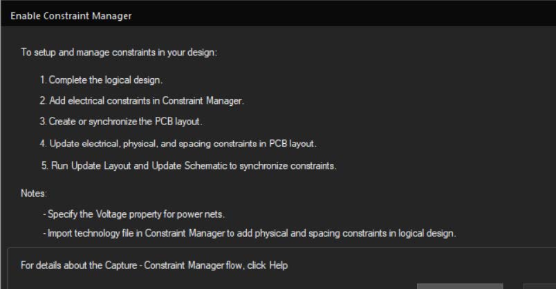
- Click OK.
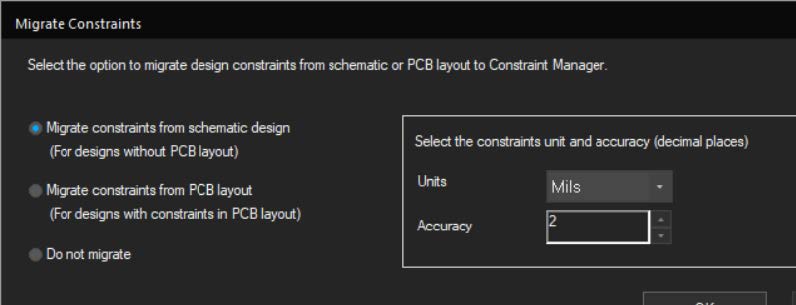
The Migrate Constraints dialog box appears. - Select Migrate constraints from schematic design.
- Specify the unit to be used for physical and spacing constraints in the Constraint Manager interface.
- Select the Do not show the message again check box to stop this message from appearing each time Constraint Manager is invoked
- Click OK.
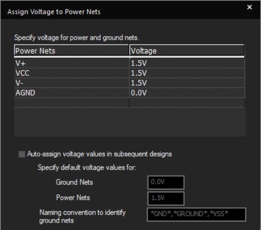
The Assign Voltage to Power Nets dialog box opens. - To identify the power and ground nets, specify the voltage values for them.
- Select the Auto-assign voltage values in subsequent designs check box to automatically assign voltages to power nets in other designs opened and Constraint Manager-enabled in the same Capture session.
- You can also specify the:
- default voltage values for ground and power nets
- naming convention to identify ground nets
The Power Nets shown in this window are the nets connected to power pins.
You can open this dialog box from SI Analysis – Identify DC Nets.Note: After enabling Constraint Manager, you can modify voltage values for nets directly in the Constraint Manager window. For details, see Modifying Voltage for Nets.
- Click OK.
The following tasks are completed:
- Constraints (if any) in the schematic design are transferred to Constraint Manager.
- Constraints Manager opens. Following screen shot is for a design that has constraints.
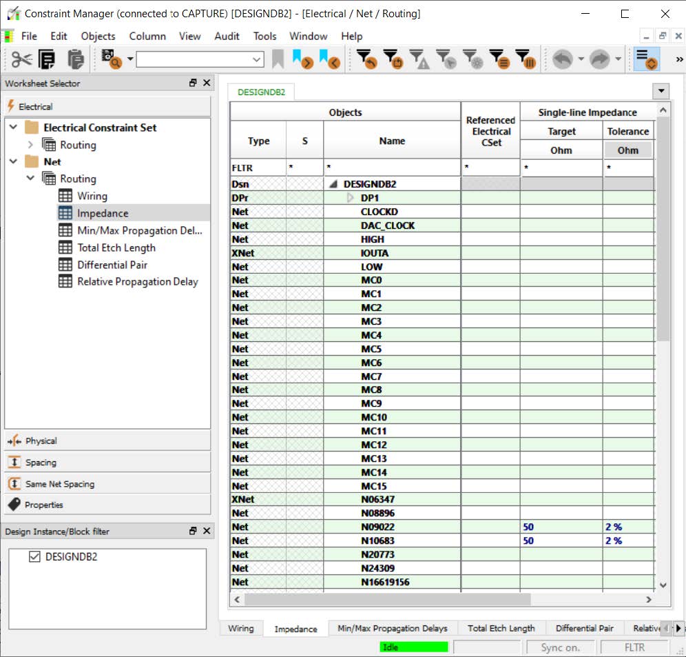
Note: It is recommended to run annotation in Capture to see the correct data in Constraint Manager.
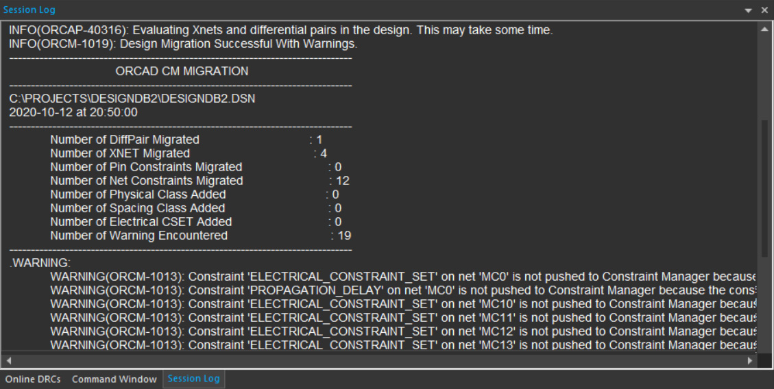
- A report is generated that shows the list of transferred constraints, constraint properties (if any), and warnings (if any).
To review the report summary, see the session log file from the Windows – Session Log menu command or the View – Session Log menu command.
If you select the Migrate constraints from schematic design option for a design that has a physical layout file, the design is enabled for Constraint Manager, and the Update Layout window opens a message to indicate that the schematic design and the physical layout are not synchronized. You are also prompted to click the Sync button to synchronize the layout with the schematic. However, this step is not mandatory.
Importing Constraints from Physical Layout
To transfer constraints from a physical layout, do the following:
- Before you enable Constraint Manager to import constraints from physical layout, ensure that you have already synchronized the design and board in the non-Constrain Manager- enabled mode.
- Click the Constraint Manager icon (
 ) in the Capture toolbar.
The Migrate Constraints dialog box appears.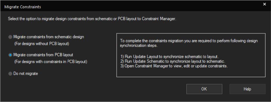
- Select Migrate constraints from PCB layout.
- Click OK.
The Assign Voltage to Power Nets window opens.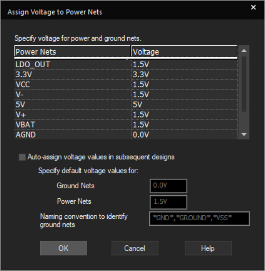
- Modify the voltage for ground and power nets.
- Click OK.
- Choose PCB – Update Layout or click (
 ).
).
The Update Layout dialog box opens.
The following message appears if the layout file is not yet Constraint Manager-enabled.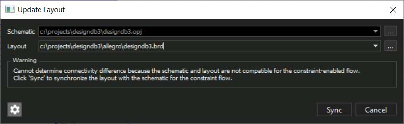
- Click Sync to synchronize layout with schematic.
After successful update of the layout file, the Constraint Difference Report window appears indicating the status of the transferred constraints. - Select PCB – Update Schematic or click (
 ).
).
The Update Schematic dialog box opens.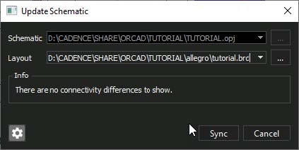
- Click Sync to synchronize schematic with layout.
The Report Summary window appears indicating the status of the transferred constraints.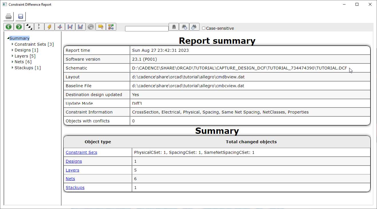
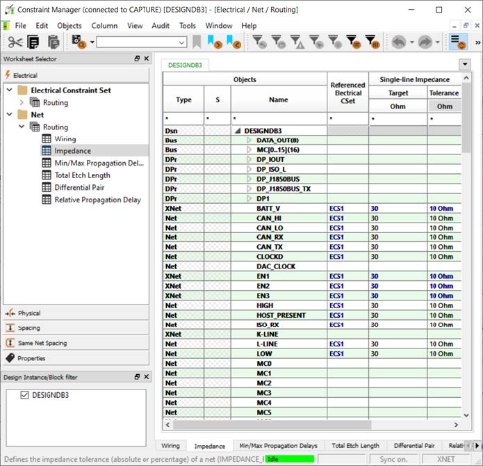
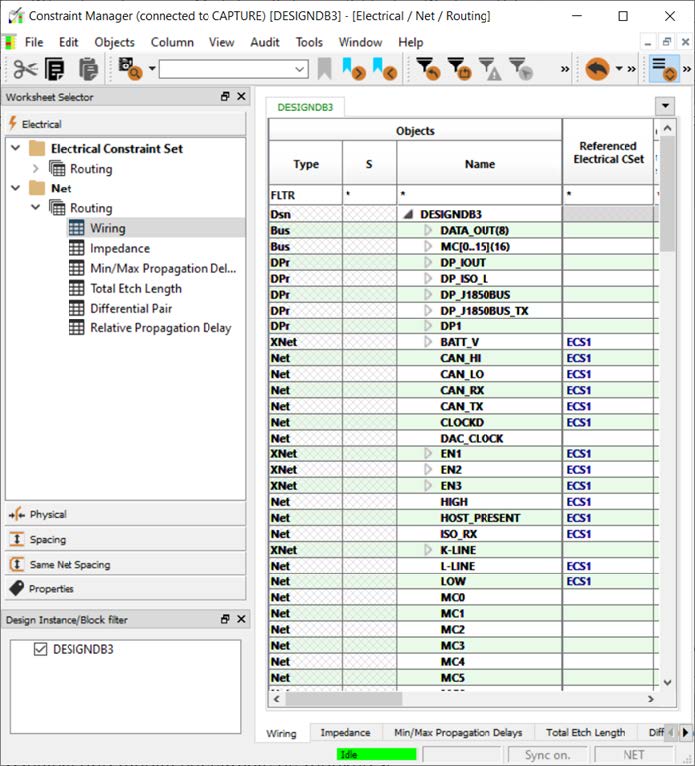
- Click the Constraint Manager icon () to open Constraint Manager.
You can see the constraints in Constraint Manager.
Note: After a successful run of the Update Schematic operation, the constraint migration process completes. Note that the nets with discrete components (even without the SIGNAL_MODEL property assigned) are converted into XNets.
You might see differences depending on the file you used to capture constraints.
Technology files (TCFX) are design independent, which means they do not contain connectivity data, such as nets, differential pairs, or buses. These files are used to initialize designs to baseline their technology. This will not backannotate any design specific data such as net groups created in PCB Editor.
The Dictionary and Constraints files (DCFX) contain all the constraint data for a specific design. These files are used to create a backup of the current constraint data for a design.
- Review and modify constraints as required.
- Save the design.
View the next document: 03 - Constraint Objects.
If you have any questions or comments about the OrCAD X platform, click on the link below.
Contact Us