The Tolerance Problem
Honestly, math is for the birds. Most birds can fly so they have me on that subject too. That said, I was an overachiever in the statistics class. That’s one of those courses you take to avoid going into calculus for another semester. Mission accomplished. So, besides being worse than lies and damn lies, statistics play a vital role in monitoring the health of our factory processes.
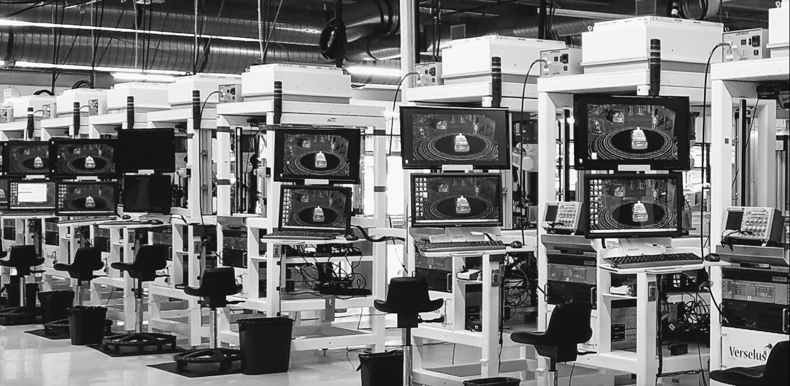
Image Credit: Author - Stacking up tolerances to ensure high performance.
There are three main factors in play that determine the results of operations. (Results = $) One is the cost of goods sold, two is the price the goods fetch and three is how long does the product last in relation to the length of the warranty. Nobody wants to do warranty repairs but there is another side to that coin.
A product that far exceeds the warranty still has room for improvement, likely in the form of cost-cutting. A lot of items are initially over-designed to allow a margin for error. The folks inclined to count beans would like to count a few more for each new and improved version. Will 5% tolerance work instead of all of these 1% resistors? Do we HAVE to derate the capacitors?
Bring on the Future
Smaller, faster, lighter, more power-efficient chips hit the market in a never-ending cycle of one-upmanship. Are chip makers down to zero microns for the gate size yet? Artificial hardware; you heard it here first. The PCB community has to step up to enable the super-chips to do their super-things. I hear from designers around the world with some impressive problems to solve. What to do what all of that current density?
Humble Brag Alert
Ok, a long time ago, we had a thermal management problem with a “friggin’ Laser”. The Mechanical Engineer (ME) had an idea of slotting the board and having a pedestal sprouting up from the aluminum housing that would be used as a heat sink. My idea was an expensive epoxy-filled via set into a pattern in the center of the PCB footprint instead of a slot. The ME’s vision included a tighter thickness tolerance on the board as well as reducing the amount of bow and twist. The explanation sounded like a quality-by-inspection plan for fabrication and an outright assembly nightmare.
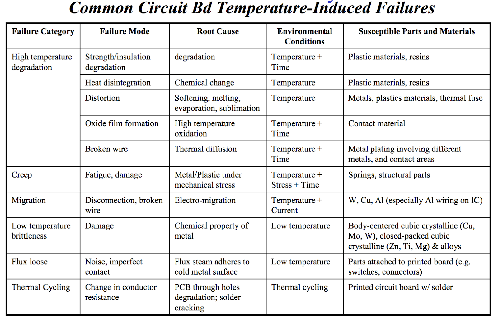
Image Credit: University of Wisconsin
You can get some PCB shops to sign up for 5% where 10% is a standard spec. Boards can often be baked under pressure and measured, and then X-ed out where they fail. The board will assume it’s natural shape and size as it goes through the harsh reflow assembly process. Anyway, long story short, the vias with strands of silver and globs of copper set in epoxy conducted the heat away better than the mechanical solution. Chalk one up for fancy board design.
Continuous Improvement
Circling back to smaller and faster, precise hole patterns are still needed for the bracket that holds the heat spreader to the device. It almost looks like a socket. It’s those mounting holes placed in the peak routing density zone. Regarding placement around these huge chips, no matter how you try to leave extra space around the device, new parts will be introduced that must be close to their pin. You will get this information in the 11th hour. If not, then at rev 2 when we find out what we didn’t know all along.
Most improvements result in a net increase in the number of parts on the Bill of Materials. Any component that can be placed further away should be, at least in the beginning. The external oscillator and bypass capacitors are fine. Memory and regulators are next. Test points, pull-up resistors? Get out of town.
The outside world can present the designer with a 3D puzzle. It only gets worse as the size matters more. At some point, you have to be convinced that all of the things that need to be done are, in fact, feasible. A timing budget comes with its own tolerance that tends to have overlapping or even competing requirements.
Tolerance within tolerance
Phase tuning a differential pair can start to exceed the maximum uncoupled length. Length disparity from placement or having to untangle the positive and negative sides of the differential pair can make it worse. It’s worthwhile to capture the various attributes with your constraint manager. Even small designs deserve to be well documented. Conforming to restricted areas can be a challenge, especially when length-matching a group of pairs. Getting all of this done with high-speed traces will require somewhere for routes to wander.
Greenspace on the board is an essential part of any good plan. Knowing exactly how far away is safe around a taller component is going to come in handy as the board fills up with components. Seemingly arbitrary rules can be expected from any device that includes the word “sensor”. Tracking these interrelationships is part of the placement routine. There will most likely be more noise sources than traces considered a victim. The electrical and physical properties of an item can take us places we don’t want to go. Here comes a problem.
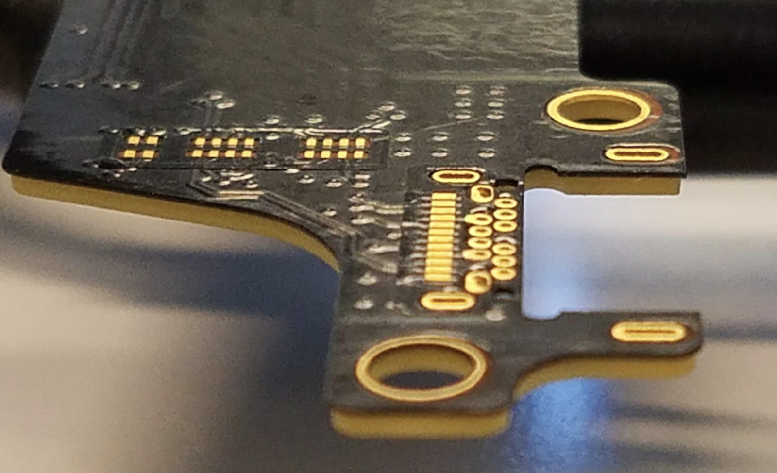
Image Credit: Author - Bonus points for flexes with tight tolerance.
For those of you interested in PCB interview questions, I would mention the tolerance problem. Riddle me this, interviewee; what do you do when the component vendor specifies requirements on their data sheet that are tighter than the factory can build in mass production? This happens with just about every device that uses USB type C connectors, for instance.
Did the connector vendor want to agree to the hole tolerances proposed by the PCB fabricator? Nope. Did the assembly team want to get in the middle? They didn’t get a choice. We ended up sourcing it as a completed flex assembly. It turns out that we were better at high-level assembly treating the flexes as units rather than assemblies.
Make sure to solve any of those lingering problems so that everyone is equally distraught. Capture the plan of record and move forward from there. Measure the critical results to see if there is stability in the process. Just measuring the key factors helps the team focus their effort on keeping the trend line between the fences. The upper and lower control limit and every value between is fair game. No lie, I had to ask, “So the parts meet spec but do not fit together?” There is a time to be casual. Product definition isn’t one of them.
Dig into the statistical analysis of the defects and concentrate on fixing the things that are costing you the most money. The fix is often about getting two or more things to play together, to fit together. That, and not bother one another; whatever the criteria, know the limits and monitor the output. Make only the adjustments required to stay in control at the factory. Paying attention is the only way to stay ahead of the birds.