Power Supply in Schematic Capture and Circuit Simulation
source: commons.wikipedia
From robots to electric vehicles to data centers and IoT devices—the one thing every circuit has in common is the need for a power supply. Different circuits will have different power demands, so mastering the fundamentals of power electronics is a key path on the road to becoming a designer. In this post we’re going to cover the basics of power supply design, schematic capture, and circuit simulation.
What is a power supply?
A power supply is simply any device that provides power to a circuit. But the definition of what a power supply is doesn’t really do justice to what it’s usually doing in a circuit. Remember how there are two types of current: alternating current (AC) and direct current (DC)?
The distinction between AC vs. DC power is an important piece of power electronics. AC switches direction within a circuit, plots as a waveform (often sinusoidal) when measured with an oscilloscope, and is used to power most buildings and homes. DC travels in only one direction within a circuit, plots as a straight line, and provides constant voltage and current to most electronic circuits such as the PCBs you design. The difference between AC and DC is the reason your laptop has a bulky external power supply between itself and the wall outlet.
Much of power electronics is about converting power from one form into another that can be safely used by the components in a circuit. Sometimes it’s going from the AC current in your wall to the DC current in your circuit. Other times it’s stepping down the voltage from a high power component to a low power component within the same board. The subfield of power electronics related to converting power from one form to another is called conversion electronics.
Here are some examples of electrical components used in conversion electronics:
-
Inverter: Change current from DC to AC
-
Rectifier: Change current from AC to DC
-
Transformer: Step up or step down the voltage of an AC
-
Converter: Step up or down the voltage of a DC
Note that sometimes the word converter is used to generally refer to any device that converts power from one form to another, whether it’s AC to DC or stepping up or down a voltage. There are also more specific terms such as cycloconverter which is used to change one AC waveform to a lower frequency AC waveform. If you’re trying to do something unique to process a current, chances are good there is a component that will do that for you.
Power Supply in Schematic Capture
So you want to design a power supply, where do you begin? An electrical schematic is usually a good place to start. It’s a wiring diagram with symbols that illustrate how the various components in your circuit should be connected together. You don’t have to worry about physical footprints, dimensions, or materials just yet, this stage is all about voltages, currents, resistances, and capacitances. It’s about creating a netlist that will function the way you expect it to.
Within the schematic editor you can create flat static designs or smart hierarchical designs. Below is an example of a schematic created with OrCAD Capture:
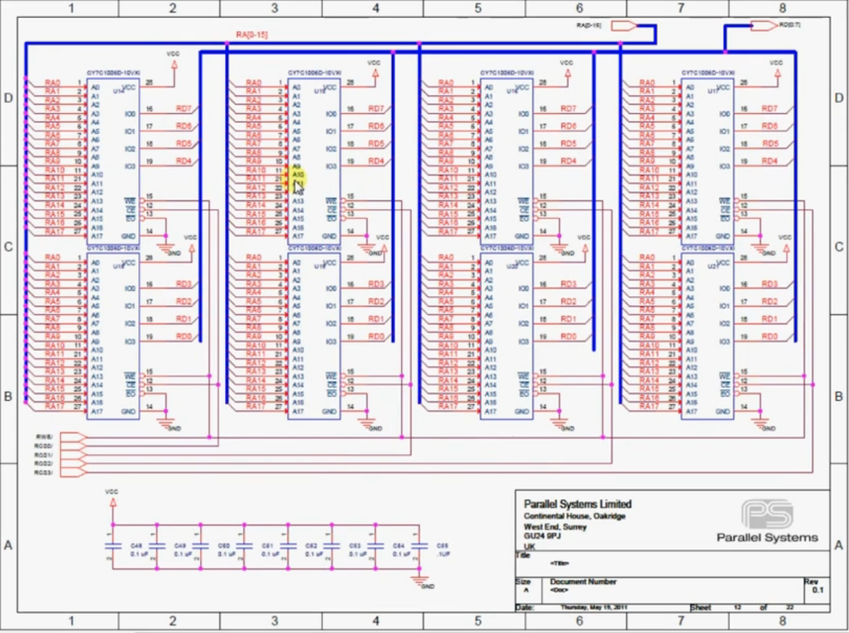
As you can see, schematics can get pretty complex. It is not always feasible to fit an entire schematic on a single page. The traditional approach to schematic capture is called flat sheet, and involves splitting a large diagram up into multiple sheets using offpage connectors to trace connections between pages. A more modern approach is to incorporate a hierarchical design which allows the designer to click on a block symbol to expand a more detailed schematic. In the context of power supply design, you’ll do well to familiarize yourself with the symbols for components related to power electronics (e.g. Vcc for voltage source).
Power Supply in Circuit Simulation
Once you’ve sketched a circuit via schematic capture, it’s a good idea to test the viability of your circuit design and power electronics. In the past, you might prototype your design using a breadboard and the physical components you had on hand in the lab. This can be a time-consuming process that is not feasible for complex designs.
Fortunately, by using circuit simulation capabilities of your EDA software, it’s possible to access an expansive library of infinite components to test your designs. Here’s a quick overview of what you can do with a circuit simulator such as PSpice, which integrates nicely as a toolbar in OrCAD capture:
-
System-level analysis
-
High power vs. low power
-
Co-simulate electrical and mechanical systems
-
Component reliability and design yield
Modern EDA software streamlines the PCB design process at every step. Check out Cadence’s suite of PCB design and analysis tools today.