What’s the Differential? Mastering the Art of the Differential Pair
You see, it’s like this. When two circuits love each other very much, they form a life-long bond and then little Diffs are propagated. Not really, but when we peruse the net names attached to the schematic symbols some net-names stand out as pairs and members of distinct groups. The most common grouping is when two nets are the same except that the last character is either a P or an N (sometimes M). Underscores often distinguish the net name from the polarity so we get things like CLK_EN_N and REF_CLK_EN_P. That syntax will trigger special handling on the PCB layout side.
There are a few considerations in play when discussing a diff-pair.
-
Line width/cross-section
-
Air gap
-
Length
-
Uncoupled Length
-
Anything else in the vicinity
Trace geometry (width, thickness) and air gaps are the drivers for impedance. Note that outer layers are the ones where it is harder to know the final copper thickness so more variability should be allowed for when using the outer layers extensively. Not only that, there is a greater chance of electromagnetic emissions (EMI) when routing on the top and bottom layers. Finally, propagation of the signal is measurably slower compared to inner layer routing.
For those reasons, the best case is usually to fan-out of the driver pins and immediately via down to an inner layer. Routing on that layer to the receiver pins and finishing with a fan-out having the same via spacing as the receiving end gets the optimal results. The exception here would be when the traces are short and direct.
The exception to the exception is when the two lines are short but not direct such that the _P and _N nets are crossed. Sometimes, there is pin-swapping possible. When that fails, my guru (small g) trick is to route the two lines as a broadside coupled pair spanning two adjacent routing layers. A quadrature hybrid coupler is an example of flipping the polarity in this way. USB Type C is the poster-boy for crossed up pairs on the legacy USB portion.

Fig 1 Image Credit: Diodes Inc.
The USB 2.0 sub-circuit down the center of the USB 3.0 connector is a case where the lines cross by design. The plus side goes from pin A6 to pin B6 while A7 to B7 carries the negative side. The main feature of this connector is that it is not polarized. There is no such thing as upside down when inserting the mating connector. Once you’ve used this type, the kind that only goes in only one way seems like an unnecessary hassle. The first time routing the middle link might look like the image below.
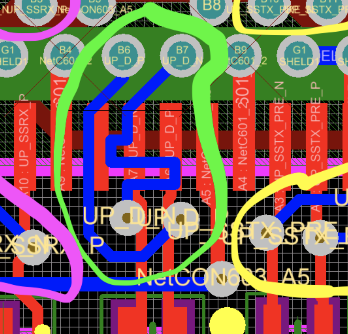
Fig 2 Image Credit: Electronics Stackexchange - That’s one way...
The central USB 2.0 _P line is routed around the crossing while the _N side meanders independently to account for the length mismatch. It’s a crude solution. Using two adjacent layers with broadside coupling allows the traces to be mirror images of one another as shown below.
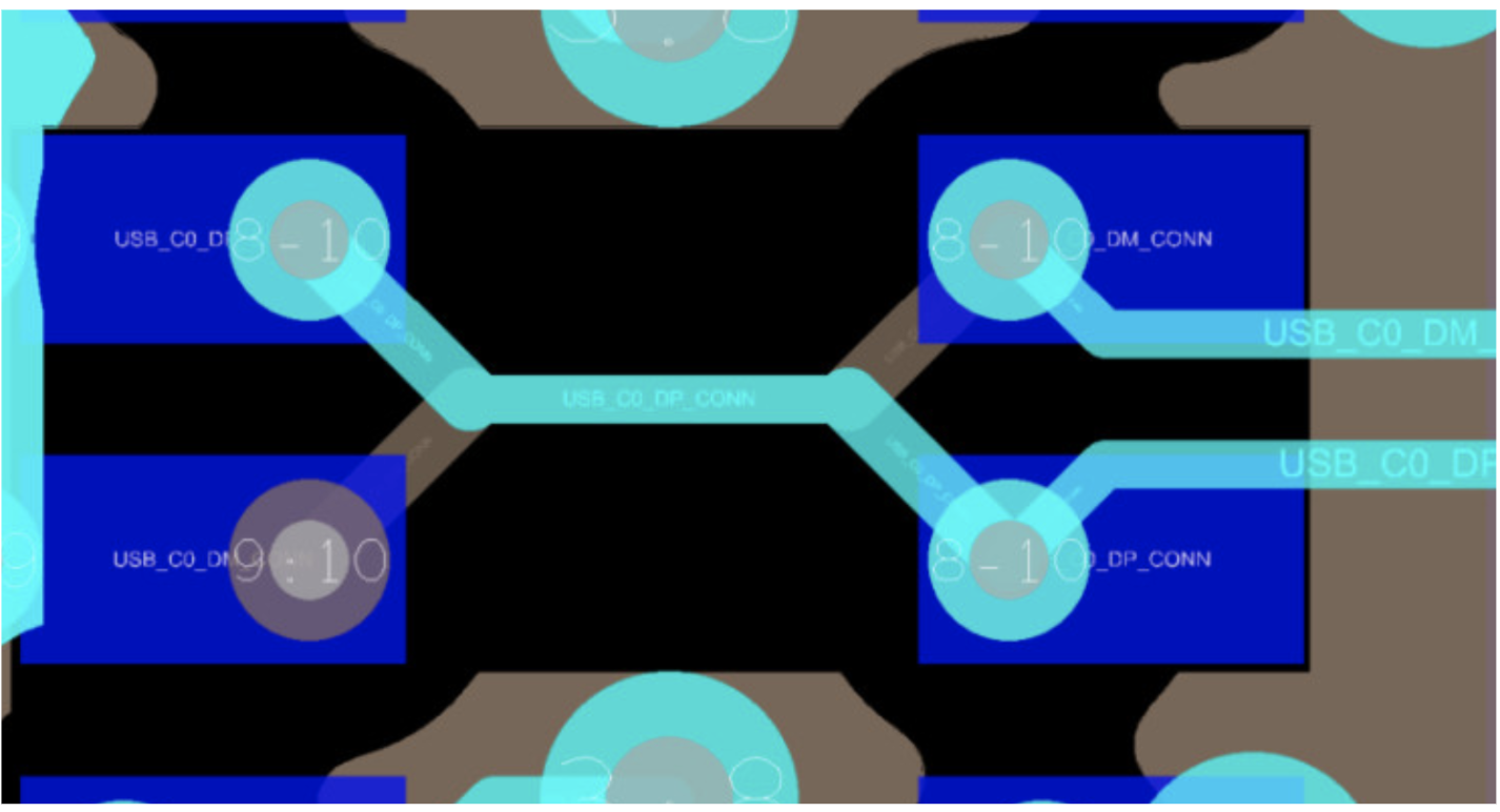
Fig 3 Image Credit: Author - A cleaner approach.
A via-in-pad solution is shown (Fig 3) zoomed in to show the use of Layer 8 (cyan) and 9 (taupe/GND layer) in a 10-layer configuration where the connector is mounted on the bottom. Clear of the cross-over, the routing continues as a normal edge-coupled differential pair on layer 8. This illustrates that there is more than one way to implement diff-pairs. A crowded pin-field is another possible use for broadside vs. edge coupled lines.
Differential Pairs Crop Up On Nearly Every design.
Certain types of Flash memory might not use differential routing. Analog designs make primary use of single-ended 50 Ohm traces but nearly everything else involves a pair or pairs of 90 - 100 Ohm differential lines. The beauty of going differential is in the name itself. Two traces with equal and opposite pulses will be more effective at ignoring what’s going on around them. Noise rejection is important in hostile environments and especially for longer length connections.
Designers use differential pairs whenever the link calls for them. In the case of automotive Ethernet, it can go either way; three pairs or a collection of separate lines. Of course, when we serialize the data for more bandwidth, we need to use differential pairs for the connections
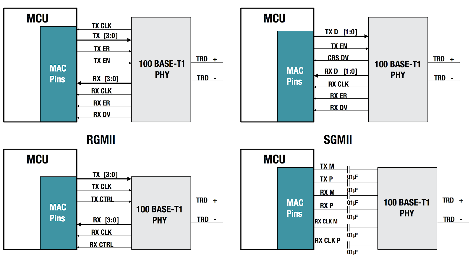
Fig 4 Image Credit: TI - Whether the MAC is six or fourteen total signals, it’s a big deal.
Tips For Better Results With Differential Pair Routing:
-
Use Symmetry to Reduce Discontinuities. Trace gathers where the lines exit pins or vias should be mirror images. It may make sense to abandon the 45-degree routing to have a clean launch.
-
Proper Ground Plane and Via Techniques for Impedance Matching: Copper pour and stitching vias create a safe place for high-speed routing. A Faraday cage is only as good as the biggest hole or slot.
-
Phase Matching and Full Bus Length Matching: Inter-pair and intra-pair timing budgets determine the degree to which we have to massage the traces into compliance. Capturing these rules pays dividends over time. Keeping the two waves propagating through the same area at the same time reduces the chance of one of the lines being hit with a transient spike that the other one missed.
-
Loose and Tight coupling: Loose coupling is defined by whether the air gap between the lines is greater than the width of the lines themselves. Loose coupling is more forgiving of certain discontinuities. Tight coupling takes up less space and requires fewer “speed bumps” to account for corners in the routing. Personally, I see the trend towards loose coupling. Be prepared for both if you have an IC that requires higher routing density in a localized area.
Using differential pairs is marginally harder than working with single-ended connections. Getting into a flex circuit scenario with rounded off traces and odd angles amplifies the difference. In the end, that’s all we’re doing is looking at the difference between two signals and determining if it is a high or a low logic state and proceeding on to the next one. There is power-saving along with the noise immunity that favors diff-pairs. If small and fast signals are your thing, differential pairs are the tracks that get you to your station.