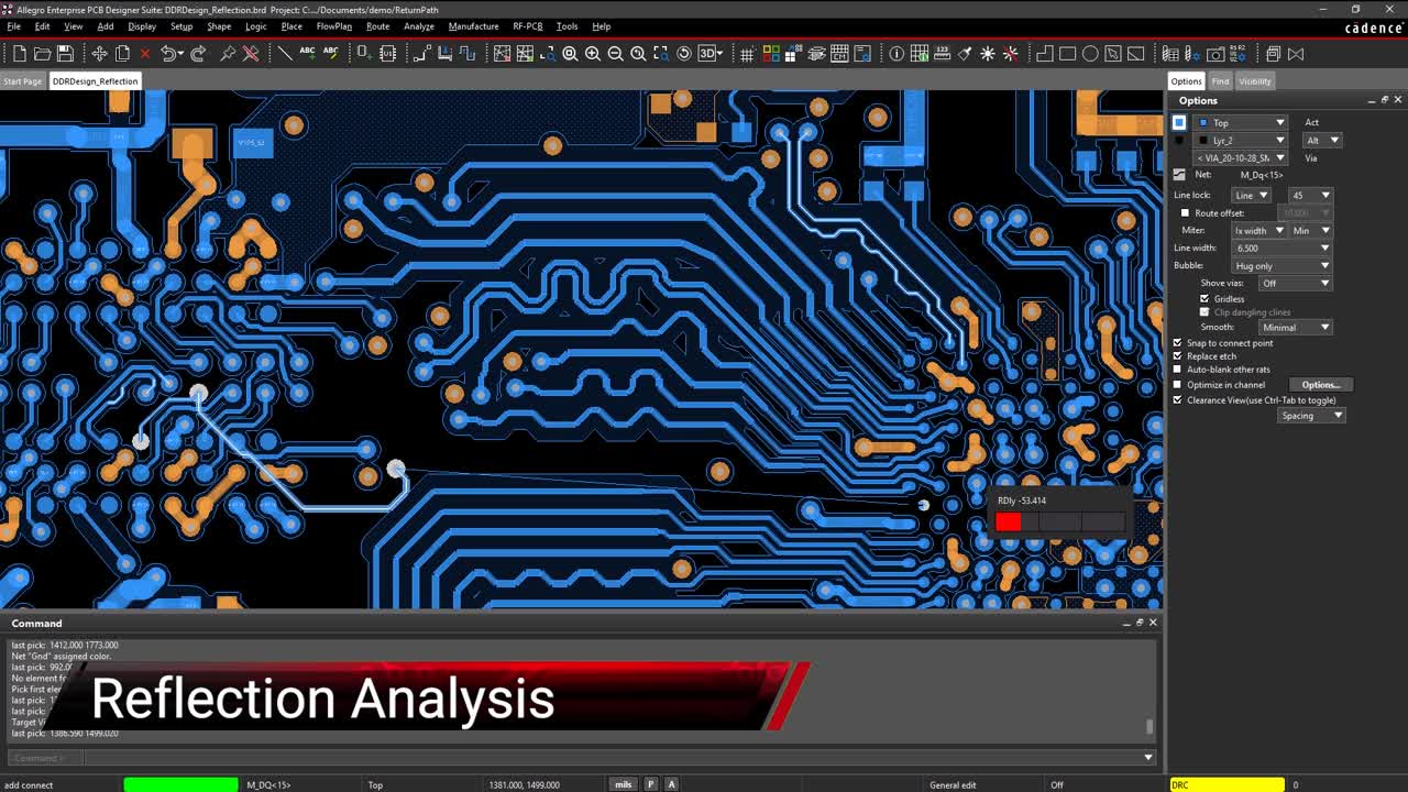
High-speed designs are vulnerable to problems such as reflection and ringing, so it’s important to simulate your designs and nip any issues in the bud.

Achieving PCI-e Compliance: Getting It Right the First Time
Other content in this Stream

Understand PWM, how to send signals from a microcontroller, and the EMI considerations when planning the duration for digital signals in your PCB design.

Check out this article for how to convert analog signals to PWM signals, as well as some design tips for analog to PWM converters.

Terahertz microcavity resonators are a critical part of on-chip microwave photonics. Here’s how these components will fit into the photonics landscape.

Harmonic motion is more complicated than sinusoidal oscillations. Here’s how complicated oscillations arise in linear and nonlinear circuits.

A look into S-parameter simulation, and discussion on how these parameters can help maintain signal integrity in RF circuits.

The use of hysteresis with comparators provides increased stability and functionality, which is essential for their proper function in various circuit types.

If you’re using a diode in an AC circuit, you need a small signal model for a diode to describe current and voltage.

Easily detect and resolve any timing issues such as delay and phase in real-time with the help of color-coded overlays on your canvas.
A Colpitts oscillator’s functionality permits its use as a VFO, such as in a superheterodyne receiver or even a spectrum analyzer, if utilizing a variable inductor.

Learn how you can tackle high-speed and high-frequency PCB designs

Your design data can be used in simulations to manage PDN impedance. Here’s how this works in PSpice from Cadence.

What’s the difference between power spectrum vs power spectral density? Here’s how these important concepts relate to your signals.

Analog signals can contain undesired harmonic components, but harmonic termination can be used to remove undesired frequency components.

Forward and reverse biasing gives a circuit designer optimal control over a diode's functionality.

You can optimize your signal chain to receive and transmit maximum peak envelope power with the right circuit simulator.

Coupled loads analysis is critical for assessing reliability of spacecraft. Here’s how the results can be used in PCB design.

Use thermal FEA simulator for your heat management problems to keep your PCB running at acceptable temperature.

There’s a lot more to grounding and voltage routing on your PCB design then simply dropping some vias, you need advanced CAD tool features to do the job right.

Verify your component choices with probabilistic design for reliability. You can use this technique to determine chances of failure in your next PCB.

If thermal management is a problem in your PCB, you can map heat flow and steady state temperature in your board with a heat finite element solver.