Voltage Divider With Complex Impedance
Voltage dividers are one of the first circuits anyone learns about in a basic circuits class. Normally this circuit just uses two resistors in series across a voltage source, and the voltage gets distributed across the two resistors. When one of these resistors is instead swapped for a complex impedance, the power drop across the two resistors will now need to consider a phase shift.
When one of the impedances is reactive, how should you analyze these components in AC circuits? These circuits do function similar to a standard voltage divider, but the reactance creates a phase difference between voltage and current that impacts the power in the resistive portion of the voltage divider. Here’s how it works and what you can expect in simulation.
General Complex Impedance Voltage Divider
In general, any voltage divider that involves reactive and resistive components can be summarized as a circuit shown below. There will always be a resistive portion (real impedance) and a reactive portion (imaginary impedance). For example, this is the case in a series RLC circuit, or just a simple RL circuit, etc.
This comes from the fact that a voltage divider involves impedances in series, so in general the impedances add up to give a resistive portion and a reactive portion. This means we could draw out the circuit as follows:
The circuit above uses a simple delineation between real and imaginary parts of the circuit. Both impedances could depend on frequency as each of these impedances could be composed of RLC sub-elements.
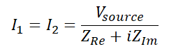
The voltage division equations for each of the impedances in the above generalized circuit are:
The fact that there is an imaginary constant in the top of the V2 equation says that the phase of the voltage in V2 will be different from the phase of the voltage in V1. However, if you calculate the total current and recall Kirchoff’s current law, you will see that the current in both impedances is:
Now we can determine the power dissipation in each of the components in the above series circuit. Using the definition P = VI* for AC circuits, the power dissipation in each of the resistive and reactive portions of the circuit are:
Just as you would expect, the power dissipation in the reactive portion is imaginary. However, the resistive portion has real power dissipation so it will dissipate energy as heat. With these relations, now we can examine the power dissipation in each portion of the circuit.
Analysis of in Each Element
The voltage, current, and power can be determined in a transient analysis simulation in SPICE. The SPICE simulation package you use should be able to mimic steady-state behavior, meaning that you are not trying to simulate the turn-on process for the circuit. Instead, you should look at the long-term operation of the circuit and how it performs over many oscillations of the source voltage.
The image below shows transient results for an example circuit where a 1200 Ohm resistor is connected in series with a 4 mH inductor for a power system. This very simply models the presence of an equivalent resistive impedance in series with an equivalent reactive impedance.
Voltages and current (yellow curve) in the resistive and reactive portions of the equivalent series circuit. The voltage division function is clearly visible as the large resistor dissipates most of the power.
Next, the power output in each section can be compared. The phase difference shown above is also illustrated in the case below, where the power dissipation is purely real in the resistive portion. Meanwhile, the power oscillates from positive (storage) to negative (release) in the reactive portion.
Going further, it’s possible to use a transfer function to determine the voltage drop across each element as a function of frequency. This would be done with an AC sweep simulation, which is a standard capability in SPICE simulators. For most instances where a design needs to operate at a range of frequencies, this will be very important for understanding the behavior as frequency changes, including the power delivery to each portion of the circuit. The phase difference between the resistive and reactive portions will always be 90 degrees out of phase as you would expect.
Whenever you want to design and evaluate the voltage division functions of series AC circuits, make sure you simulate your designs with the complete set of tools in PSpice from Cadence. PSpice users can access a powerful SPICE simulator as well as specialty design capabilities like model creation, graphing and analysis tools, and much more.
Subscribe to our newsletter for the latest updates. If you’re looking to learn more about how Cadence has the solution for you, talk to our team of experts.