Home
Free Trial
Home
Free Trial
Read More
Content
Filter
10 results found
Featured
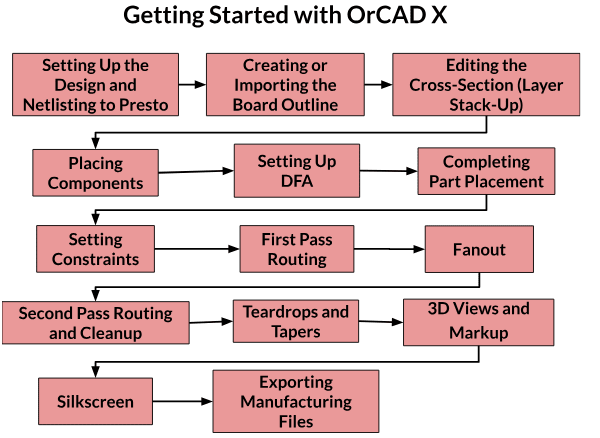
Guide to Getting Started with OrCAD X Presto
Featured
Generative AI For PCB Design with Allegro X AI
Featured
PCB Design Documentation for Successful Boards
Featured
Common PCB Tolerances for Manufacturing
Featured
Unified System for PCB Design Documentation in PCB Workflows
Featured
Cloud Data Management Capabilities With OrCAD X
Featured
Simple PCB Layout Design: Tips and Strategies
Featured
Best Engineering Document Management Software Top Features
Featured
What Makes an Industry Standard PCB Design Software?
Featured
PCB Layout Efficiency with OrCAD X Tools and Workflows
Featured
Products
None
OrCAD X
(2)
Allegro X PCB
(1)
Content types
None
Blog
(10)
Solutions
None
PCB Layout
(8)
Artificial Intelligence
(1)
Data & Process Management
(1)
Schematic Capture
(1)