Mixed Signal PCB Design Guidelines for Circuit Board Layout
Key Takeaways
-
Placing components in a mixed signal design.
-
Mixed signal PCB design requirements for power delivery networks.
-
Routing traces on a mixed signal PCB layout.
Some of the routing that may be part of your mixed signal PCB design
Electronics used to be made up of multiple circuit boards that each handled different functions of a design. Digging into one of these older systems may have revealed a processor board, a power supply board, audio and video cards, and even a fan control PCB. With the desire for smaller electronics, greater functionality, and the need to reduce manufacturing expenses, many of these multi-board systems have been replaced with one mixed signal design.
At first glance, a mixed signal PCB layout is essentially the same as any other layout. Parts have to be placed, nets have to be routed, and power and ground planes have to be connected. However, once you look a little closer, you will see that there are some unique requirements that can present a design challenge if you aren’t prepared for them. We'll lay out these requirements in these mixed signal PCB design guidelines to help you out on your next design.

Component Placement in Mixed Signal PCB Layouts
When preparing to lay out a mixed signal PCB design, it is essential to develop a floorplan of the design before you start placing components. There are many methods of creating a floorplan that range from drawing on the back of a napkin to using advanced CAD software. Whichever way you choose, developing a floorplan first will help you partition the different circuitry areas so that their signals don’t mix when you lay out the PCB. This step is important to minimize noise problems such as crosstalk and EMI between the board's digital and analog sections and, in general, improve the overall signal integrity of the design.
With the board's circuitry now partitioned, you can begin to place the components. Mixed signal layouts are like any other PCB design, and parts will need to be placed according to industry-standard rules and clearances. However, there are some unique mixed signal considerations to be aware of while you are placing the parts:
-
Maintain the partitions: Keeping sensitive digital and analog components and routing separated from each other is essential for creating the best signal integrity. It can be very tempting to alter the floorplan, and in most cases, you will have to do some alterations, but you must keep the different circuitry isolated from each other.
-
Larger processor and memory components: These parts take up a lot of room, require a lot of routing, and generate a lot of heat. They need to be located more in the center of the board for thermal dissipation and close to their related circuitry for the best signal integrity performance.
-
Bypass capacitors: The need for power integrity is especially important in a mixed signal design, which can be assaulted by ground bounce and power spikes. To counter these effects, each supply pin on a processor will usually have its own bypass capacitor assigned to it. These caps must be placed as close as possible to their assigned pins for short and direct routing.
-
Associated parts and routing: Usually, there is a signal path laid down in the schematic for the sensitive circuitry of the processor and memory devices. Starting with the connectors, each part needs to be placed around the processor and memory chips to preserve the signal paths of the schematic.
-
Power supplies: The circuitry of each power supply needs to be isolated from sensitive digital and analog circuitry, while at the same time being located close to the devices they are powering. There should also be a separation between these supplies to help balance the board thermally. Power parts need to be placed as close to each other as possible within each individual supply to create the best power integrity in the design.
While we’ve been talking about the electrical needs of a mixed signal design, the board will still need to be manufactured efficiently for the highest yields. Therefore, following all of the design for manufacturability (DFM) rules is also necessary while placing parts for the best signal and power integrity. Another critical aspect of the layout is the design of the power delivery network, and we’ll look at that next in these mixed signal PCB design guidelines.
Different types of circuitry are now routinely combined on one circuit board
Mixed Signal PCB Design Guidelines for Power Delivery Networks
One of the reasons for focusing on partitioning the design is to create a very robust ground system for the circuit board. With the board having different types of circuitry in it, one question is whether designers should use separate or split ground planes for the digital and analog areas of circuitry. If the analog and digital circuits are completely isolated from each other or if the board is generating high-voltage currents, it may be helpful to create separate grounds. However, separating the analog and digital ground of a standard mixed signal circuit board is more likely to introduce new EMI problems than keeping the grounds on one plane.
Ground planes are necessary to provide clear signal return paths for the design. On a standard mixed signal design where there are signals that cross between the two areas of circuitry, the return paths of these crossing signals will be broken by separated ground planes. Separate ground planes will most likely force the signal to find a new path back through cables, shielding, or the system’s frame, creating a lot of additional noise in the process. To avoid signal and power integrity problems like these, the best ground configuration for a standard mixed signal design is to use one unbroken ground reference plane that is not split. With a carefully partitioned component placement and the speed of digital circuitry today, the return paths will naturally stay close to their outbound signal routing as long as the return path isn’t obstructed or broken. In addition to being the best configuration for signal return paths, there are several other advantages to a single ground plane as well:
- They shield the design’s sensitive circuits from incoming EMI.
- Their shielding also prevents any internal interference generated by the board from escaping.
- A large plane creates a lower impedance ground system than smaller planes or traces.
- A large plane will also help dissipate heat from large processor chips or power supply components.
You can split the planes when working with the power nets as long as you provide a robust connection to all power pins. Do not choke off a pin's supply of power or you may end up with power integrity issues and a hot connection. Make sure to use short wide trace routing to connect power components together, and keep these power components and connections all on one side of the board to minimize inductance. And speaking of trace routing, let’s look next at some other guidelines for routing a mixed signal design.
Managing design rules and constraints are an essential part of a mixed signal PCB design
Trace Routing in a Mixed Signal Design
With the board carefully partitioned, the components located in their optimum positions, and a robust ground system in place, most trace routing will naturally follow the right paths. However, there are some trace routing guidelines for mixed signal PCB design guidelines for routing to be aware of:
- Keep signal paths short and direct.
- Follow the signal path of the schematic, especially in high-speed circuits.
- Be careful of creating antennas with the routing of traces and vias.
- Power supply routing should use short, direct, and wide traces to reduce inductance.
- Make sure to keep the routing of digital circuitry isolated from analog circuitry, and vice versa.
- Make sure there is a clear signal return path available on the reference plane for routing, and especially those traces that go between the digital and analog circuitry areas.
Trace routing on a mixed signal design is one area where it is essential to set up and use your design rules and constraints. PCB layout tools like Cadence’s Allegro PCB Editor provide their users with a full constraint management system (as shown in the picture above) to set up trace routing widths and other critical design rules. Next, we’ll look at some other features in the PCB design tools that will help with mixed signal PCB layouts.
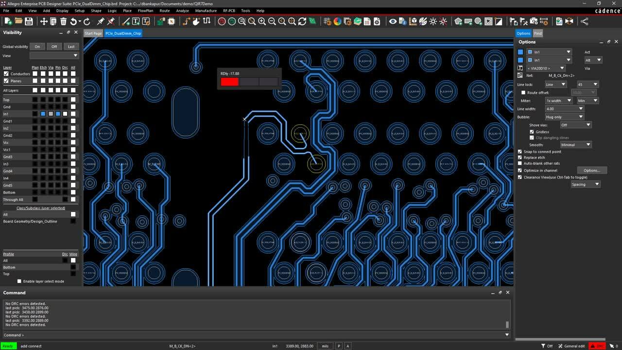
The IR Drop feature in Cadence’s Allegro PCB Editor can help with your PDN design
CAD Tool Features That Are Essential for Mixed Signal PCB Design
We’ve already seen the importance of using a constraint manager for setting up design rules for trace routing. When routing mixed signal designs, this can be a great help with all the different trace widths required for standard routing, differential pairs, impedance controlled traces, different analog signals, and power and ground traces. But trace routing rules aren’t the only rules that Cadence’s Constraint Manager controls. It will also control component clearances, via types, testing constraints, and even electrical attributes such as signal integrity and timing.
There are other features in PCB layout tools that can also help you in your work. These include 3D viewing and checking capabilities and a host of simulation tools that can be used while the design is still in layout. In the picture above, you can see the IR Drop Vision viewer, which will help you ensure that all of your connections receive the proper amount of power delivery they need for their function. IR Drop Vision is the first step to a complete PDN analysis of your mixed signal PCB design and can help you avoid costly debugging and testing with multiple prototype builds.
For more information on PCB design and how to work with your board’s PDN, check out this E-book from Cadence.
If you’re looking to learn more about how Cadence has the solution for you, talk to our team of experts.