Working with SPICE Model Parameter
Key Takeaways
-
SPICE models define electrical behavior using parameterized equations, while subcircuits represent interconnected components.
-
Custom models can be created in PSpice using datasheet values for diodes, transistors, and more.
-
Parameters like forward current, breakdown voltage, and capacitance are critical for accurate simulation results.
Common circuit components and passives usually have simple SPICE model parameters that define the output voltage and/or current as a function of the input signals. These models might define the impedance (e.g., for capacitors and inductors) as a function of frequency, which allows for AC simulations. Unfortunately, complex components may not include a SPICE model, and you may need to build a SPICE model for components if you want to use them in circuit simulations.
What’s in a SPICE Model?
|
Sources |
Components |
|
These describe voltage/current sources in your circuit, which can be modeled as transients, piecewise linear, sinusoidal, pulsed, square, triangular, or sawtooth waves. Sources can be modeled as dependent or independent sources. |
These receive input from a source or from the output of another component. Components are defined using terminals, and the relevant terminals in your SPICE model should match the component pins you see on your schematic. |

Commented and Continued Lines
A SPICE model begins with commented lines of text that describe the circuit or component being created. These lines may contain author information, revision dates or numbers, and any other information a user needs to understand the model.
-
Commented lines: A line beginning with an asterisk (*) is commented out and is not read by the simulation program. If a semicolon (;) is placed in the middle of a line, everything after the semicolon is commented.
-
Continued lines: If a line begins with a plus sign (+), this line is meant to be a continuation of the previous line. This is standard usage for indicating each SPICE model parameter as part of a component model. The SPICE model parameters are defined for a model using these continued lines.
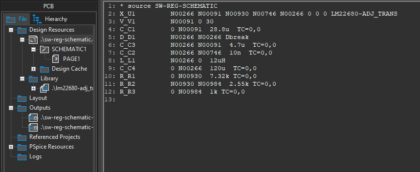
The SPICE netlist is an amalgamation of descriptions of the circuit elements. It will typically contain a list of objects, such as the letter for the circuit element, the node registers, the model names, and then corresponding component values. A MOSFET, for example, may have a drain, gate, source, and body along with length and width values, threshold voltage, and transconductance parameters.
Models vs. Subcircuits
|
SPICE Model |
Subcircuit |
|
- Uses a mathematical equation to generate an output voltage or current from a given set of inputs and model parameters. - Can describe component behavior for standard components (e.g., BJT, diode) or allow the model author to write an explicit equation relating inputs/outputs. - All SPICE models are declared using the .MODEL statement. |
- A textual (netlist) representation of a circuit composed of standard circuit elements. - You can export a group of components from a schematic as a subcircuit and then assign it to a specialized component in your design. - Subcircuits can call other subcircuits within the same file (e.g., SCKT1 and SCKT2 both call SCKT3). - All SPICE subcircuits are declared using the .SUBCKT statement. |
Example SPICE Model Parameters
Some common components can have quite complex SPICE models with multiple parameters. This is more visible when looking at the equations describing the electrical input/output relationships. Here are some examples of more complex SPICE model parameters you’ll find for transistors, which form the basis for many SPICE subcircuits you’ll need to build for your components.
Large and Small Signal Transistor Models
Transistors will use two different SPICE models, depending on whether the transistor will operate in the large-signal or small-signal regime. When an input is applied to the base (or gate for MOSFETs), the operating point moves away from the bias point along the transistor’s load line.
|
Small-signal parameters describe the transistor’s response when the operating point moves within the linear region around the DC bias point. This is important if an AC signal is applied to the base/gate, as a large amplitude will cause the collector/source current to saturate. |
|
If your transistor will operate anywhere from the linear regime into saturation, you’ll need to define large-signal model parameters for your transistor as part of your subcircuit. The full set of 28 SPICE model parameters for BJTs allows you to model transistor behavior in the linear and saturation regions. |
The relevant model parameters are meant to capture the following aspects of the transistor.
-
Material properties: Includes aspects such as the electronic bandgap, transport saturation current, doping gradient, and built-in voltage.
-
Temperature coefficients: These values define how the electrical parameters in the model change as power is dissipated in the channel.
-
Zero-bias capacitances: The base-emitter and base-collector capacitances need to be defined, as well as the forward-bias depletion capacitor coefficient.
Once you’ve defined these parameters for your SPICE model, you can build a subcircuit for a component by referencing your transistor model.
SiC MOSFETs
SPICE model parameters for SiC MOSFETs are similar to large-signal transistor model parameters, but they also include channel geometry and more fundamental material parameters.
-
The focus on material parameters like mobility and gate oxide thickness is important because there is no single model for SiC MOSFETs.
-
Different models are used to describe SiC MOSFETs and SiC-GaN MOSFETs, and each requires different parameters. Because these components are new, describing them with SPICE models is still a significant subject in the research community.
-
Some manufacturers of SiC MOSFETs provide SPICE models for their components, which can then be used to model similar components by editing the SPICE model file.
The SPICE model parameters for this MOSFET are extensive.
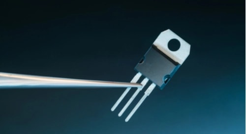
Diode Models
The internal structure of semiconductor diodes means they can be quite complex. Overall, diodes require 15 SPICE model parameters for an accurate description of electrical behavior. These same 15 parameters apply to Schottky diodes and p-n diodes. Examples include breakdown voltage and current, saturation current, and lead resistance.
More Complex Components
Components like phototransistors, CCD arrays, ADCs, and relays can be described as subcircuits or phenomenological models. The approach you need to take depends on the complexity of a component and whether there is enough information in a datasheet to build an accurate electrical model.
|
Going the phenomenological route is easiest as you are simply producing an equation (usually polynomial) that reproduces some performance graph from the datasheet. However, there is a risk of producing some errors when the device is operated outside the range used to build your mathematical model for the component. |
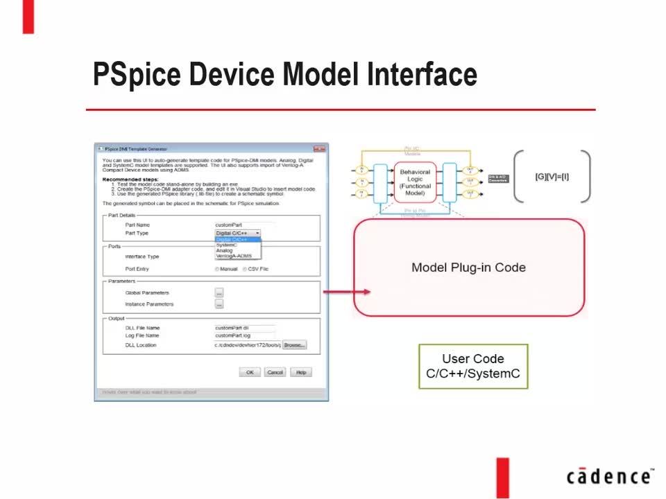
Extracting SPICE Model Parameters For Use in a PSpice Model
PSpice is an advanced SPICE simulation software bundle with OrCAD X. In this tutorial, we'll walk you through how to create a custom PSpice model using datasheet values—specifically using a diode as our example. While we're focusing on a diode here, the same process applies to most other semiconductor devices like BJTs, MOSFETs, and Zener diodes.
1. Open PSpice Model Editor
-
-
Launch from the Cadence program menu.
-
Choose the default design entry as OrCAD Capture, then click Done.
-
Creating a new Model in PSpice
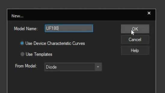
2. Create a New Diode Model
-
-
Go to File > New > Model tab → click New Model.
-
Name the model (e.g., UF180).
-
Select “Use device characteristic curves”.
-
Set the device type to Diode and click OK.
-
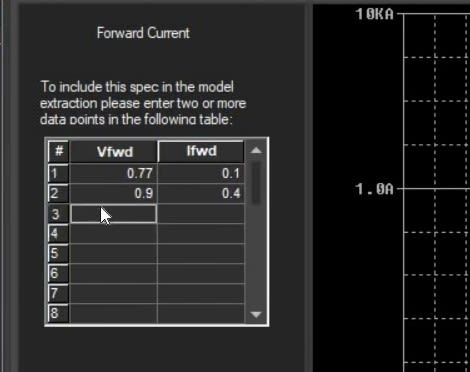
3. Enter Datasheet Parameters
-
-
Use the diode datasheet to enter the following in their respective tabs:
-
Forward Current: Input Vf and If data to update the I-V curve.
-
Junction Capacitance: Input values at various reverse voltages.
-
Reverse Leakage: Add leakage current vs. voltage data.
-
Reverse Breakdown Voltage: Enter Vz (e.g., 800V).
-
Reverse Recovery Parameters: Input if known (or contact vendor).
-
-
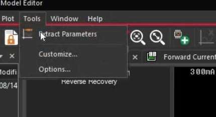
4. Extract Model Parameters
-
-
Go to Tools > Extract Parameters.
-
View all extracted parameters.
-
5. Save the Model
-
-
Go to File > Save As.
-
Choose location (e.g., create folder new_diode on Desktop).
-
Name the file (e.g., diode.lib) and click Save.
-
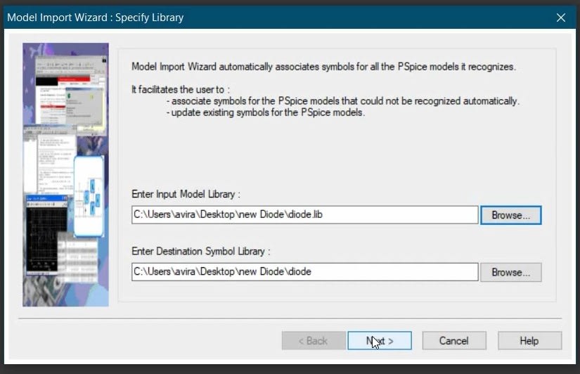
6. Assign a Symbol to the Model
-
-
Reopen PSpice Model Editor.
-
Go to File > Model Import Wizard.
-
Locate the saved .lib file.
-
Set output folder (can match input).
-
Click Next, then Finish to generate the symbol.
-
7. Use the Model in Simulations
-
-
Add the new symbol to your PSpice library.
- Start using the custom diode model in simulations.
-
How to Edit a PSpice Model and Run a DC Sweep Simulation
You might need to edit a PSpice model when the default component behavior doesn’t match your design requirements. This could include adjusting a diode’s breakdown voltage, modifying a transistor’s gain, or customizing a manufacturer-provided model to reflect real-world conditions more accurately. This allows for more precise simulation results tailored to your application.
Steps to Edit a PSpice Model
1. Select the Component in the Schematic: In your OrCAD Capture schematic, right-click the component you want to modify (e.g., a diode).
2. Open the PSpice Model: Choose "Edit PSpice Model" from the menu.
-
- The PSpice Model Editor will open with the model definition for that component.
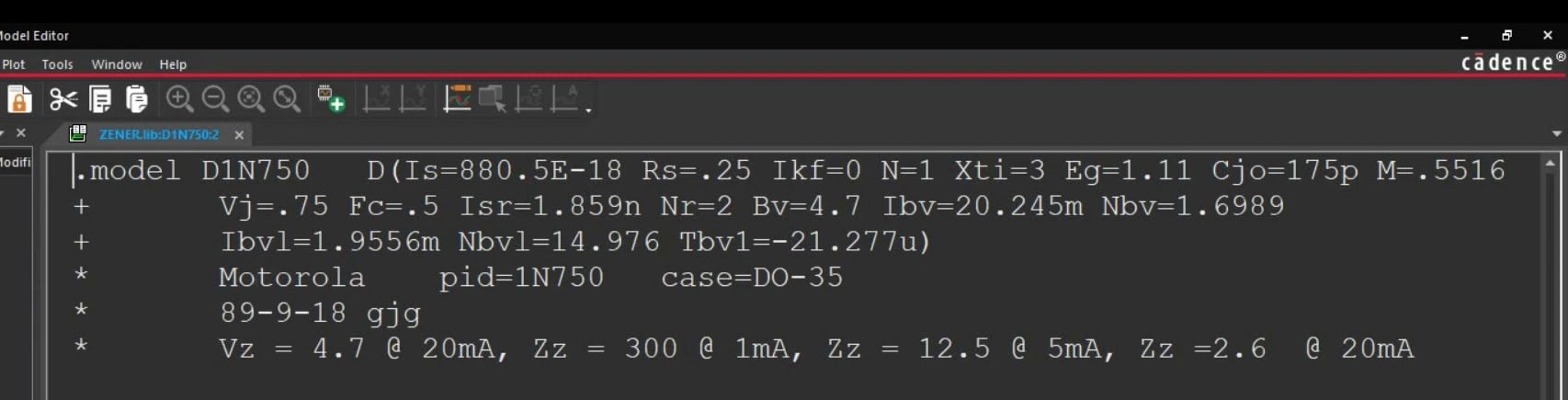
Editing model parameters in PSpice
3. Modify the Parameters: Locate the parameter you need to change (e.g., BV for breakdown voltage).
-
-
Edit the value directly in the model text (e.g., change BV=4.7 to BV=8).
-
4. Save the Model
5. Close the Model Editor
6. Re-run the Simulation
The simulation will now use your updated model parameters.
Accurate simulation starts with the right SPICE model parameters. OrCAD X supports model creation and customization through PSpice, allowing designers to define behavior for components. Whether you're working with vendor-provided models or building from datasheets, OrCAD X simplifies the process. Explore the full capabilities of OrCAD X, or get started with a free trial to build and simulate custom SPICE models today.
Leading electronics providers rely on Cadence products to optimize power, space, and energy needs for a wide variety of market applications. To learn more about our innovative solutions, subscribe to our newsletter or our YouTube channel.