The Case For Using Copper Pour on Routing Layers
Doing special things with a circuit pattern is a hallmark of analog design. All of the important signals on the board added together are equal in importance to one net; that net is the ground net. Every active component will have on at least one of its pins tied to ground. An RF device could use any of a number of voltages and will likely want a dedicated power supply for each voltage required. Characteristic impedance relies on a ground plane or two.
As we go for faster digital circuits, they also start to behave like their analog counterparts. The typical routing rules involve fanning out the surface mount pins with short segments and doing the main course of the routing on an inner layer. An especially elegant placement could make it possible for the bus of related traces to run entirely on the outer layers.
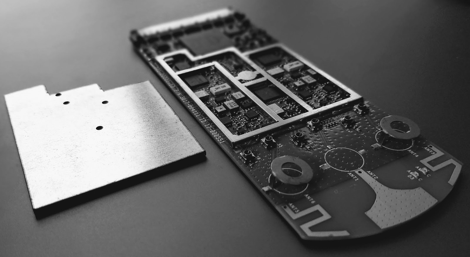
Image Credit: Author - WIFI to the rescue!
In that case, we don’t get to sandwich the traces between ground planes to stifle electromagnetic radiation (EMI). The saving grace is that we don’t use vias to transition the signals to inner layers. Printed Circuit Board design is always a balancing act. We use vias anyway but in a different way. Wrapping the bus in a full metal jacket on the outer layer and staking the edges of the ground plane to inner layer ground is usually sufficient to meet the EMI specifications where short digital traces are concerned.
When to Use Caution
Ground pour that is not accompanied by ground vias can become a conduit for crosstalk between the traces on either side of the ground shape. Removing that copper leaving the excess air-gap is better than an unsupported metal icicle to serve as an antenna between two lines whether they are aggressors (noisy) or victims (sensitive to noise).
Clocks are one of the things you can count on to be noisy. Receive chains on their way to the input pin are possibly the worst in terms of being a victim. It isn’t always that obvious. Reset lines and other sundry circuits can generate noise. Pretty much, any kind of sensor is going to be a victim, even when the aggressor is routed several layers below the sensing device. Consider the entire board around a sensor to be a no-man’s land in terms of circuits not related to the sensor. As always, read the relevant datasheet’s application notes regarding layout.
Outer Layers
We often label our metal layers in a PCB categorically. The outer pair of layers are known as primary and secondary placement layers. The primary placement layer can be top or bottom, it depends on which one has the greater number of components. It could also depend on a definition from the physical design team. If the busy side of the board is facing downward in the enclosure, then it will likely be labeled as the bottom but would be considered the primary side.
Image Credit: bigstock
No matter the context, the component placement layers offer the best possible location for using a copper flood as a passive heat sink. Through-hole or surface mount pins can attach directly to a shape. For better solderability, the shape can be defined with a clearance plus spokes that tie the pin or pad to the outer layer ground planes.
Free Reliability Through Thermal Performance
Almost every component on a PCB is capable of generating heat as does its work. The hottest location in the system is right where the chip attaches to the substrate or interposer. The junction temperature at that point determines the lifespan of the component and, thus, the system. A strong layout provides the thermal path to success.
When the electromagnetic radiation is well shielded, the system’s emissions go down. That effectively reduces power consumption. All of your good impedance practices contribute to the efficiency of the power domain. The component doesn’t have to work as hard when there are fewer discontinuities. It’s a little thing that adds up over time.
Uncontrolled thermal excursions can lead to early failure. Early failure leads to warranty work or product replacement on your dime. Fixing or replacing previously sold items cuts into whatever profit margin came from the initial sale. Lower profit leads to all kinds of bad things, ultimately going out of business. Don’t go out of business. Get busy with the planes.

Image credit: Author. Perpetrator: unknown -You go on vacation, you come back to a well-shielded workstation
On Slots
A technique that was taught to me at Qualcomm was to break the plane around an external oscillator with a gap that cuts the ground around the device and its posse of resistors. The three sides that are not connected to the processor are framed by the void. This will help confine the oscillator’s switching noise.
I always say put in some ground vias near any slots. In this case, you would be providing an escape path on the next ground plane for all of those oscillations to propagate their heartbeat on to some unsuspecting transmission line. So back off on the ground vias a bit on the quiet side of the gap. Maybe even repeat the gap on the first inner (layer 2) ground plane if there are no traces running through there on layer 3. Reroute them if possible so you can trap the noise and coral it back to the device.
Inner Layers
When you flood a layer with significant routing on it, there are bound to be some areas that wind up isolated. The way you group the traces will have a profound effect on the outcome of the ground flood. The first thing I want to do is to set a wider gap rule between the copper flood and the traces or shapes.
Backing off will keep the traces from becoming a coplanar line of unknown impedance. I use 0.50-millimeter pull-back; about double what would be typical on the actual ground plane layers. Some busses get 1 mm if they are long or have higher data rates. It also helps to set a larger aperture so that the copper cannot even get between two traces that are fairly close together.
Managing the copper “islands” is a matter of setting a higher threshold for the minimum size. A blob of copper that has a single ground via in it isn’t doing any good. When it comes to power plane layers, there is room for ground pour as well. Let’s say you have a nice frame of ground vias around the perimeter of the board. Well, pull back the voltage plane and add a frame of ground that joins the stitching vias and completes the Faraday cage around the power planes. Your compliance team will see that and you regard you as a Saint. Manage it carefully but don’t be afraid of the Ground.