Improve Reliability Using Design Rule Checks in PCB Design With OrCAD X
Key Takeaways
- OrCAD X offers extensive DRC features like same net spacing, via constraints, and package-to-package spacing.
- OrCAD X provides both online and batch DRCs, offering real-time feedback and comprehensive error reporting.
- The tool’s interactive features, such as zooming into errors and an overview panel, streamline the correction process.
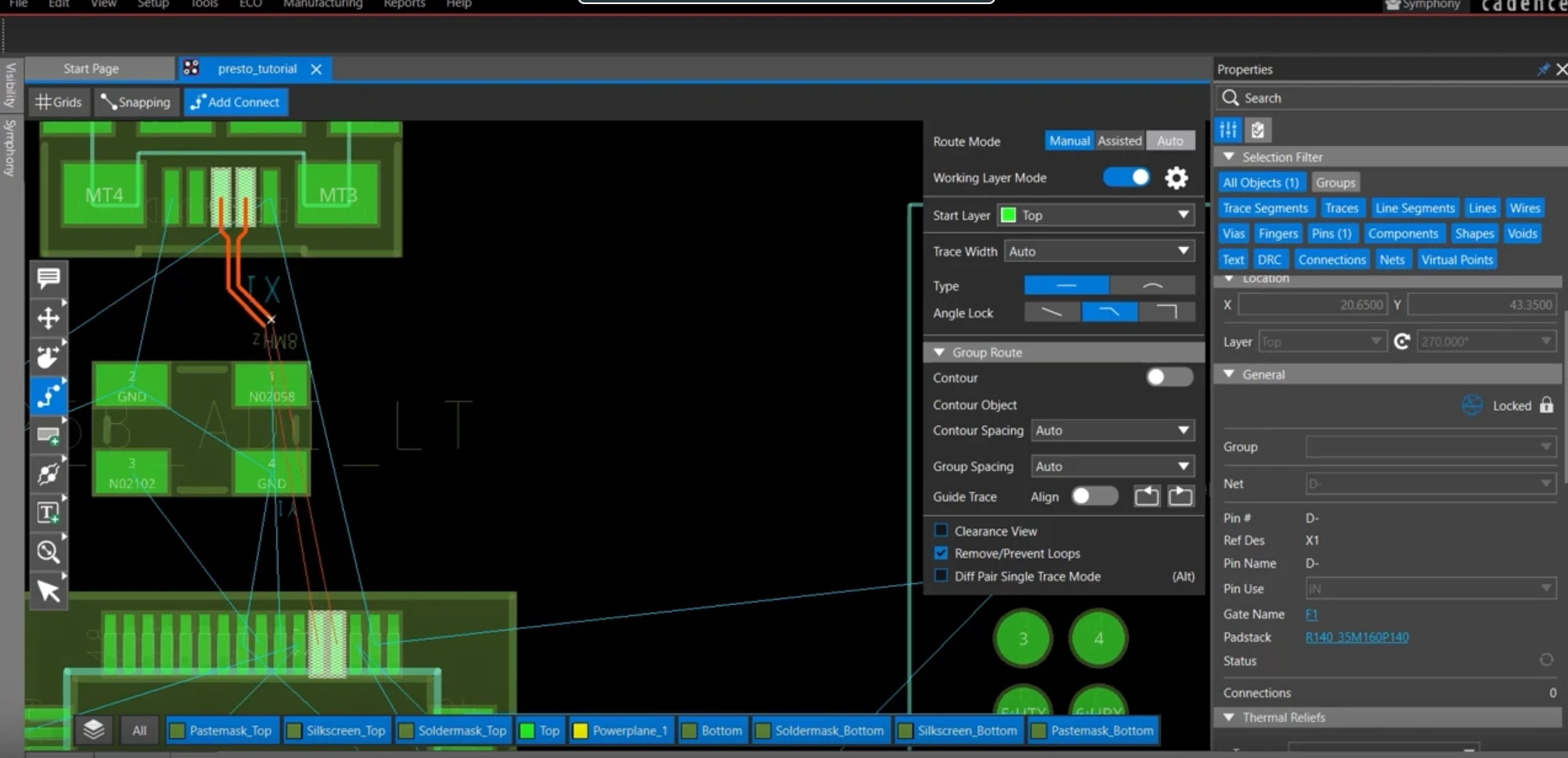
DRC violation highlighted and marked while routing in OrCAD X.
A design rule check (DRC) is a set of rules a designer can use to ensure their PCB matches all the dimensional tolerances and manufacturing considerations they set for a board. It’s important to account for these natural variations in production by adding enough margin to your design.
To ensure manufacturability before sending designs to the fabrication house, perform a design rule check in PCB throughout your design process to avoid these errors. What follows is a crash course on DRC, and how it can help you improve your acceptable manufacturing yield.
Types of DRC Features Present in OrCAD X
|
DRC Feature Group |
Feature Name and Description |
|
Spacing Constraints |
|
|
Line Width Constraints |
|
|
Via Constraints |
|
|
Net Constraints |
|
|
Annular Ring |
|
|
Component Placement and Lead Checks |
|
|
Fiducial and Outline Constraints |
|
|
Cutout Constraints |
|
|
Design for Manufacturing Constraints |
|
How Can PCB DRC Checks Aid in Design
A PCB DRC check lets you verify that your schematic and layout actually reflect the design margins you wish to incorporate in your design. When one of these design margins is violated, the DRC tool will let you know by flagging the error on your schematic or layout.
Where DRC Rules Occur: Schematic and Layout
DRC only checks the validity of your initial schematic, and whether it can be manufactured with a good yield. Electrical Rule Checks (ERC) are used at both the schematic and layout levels to ensure the device satisfies electronic design rules such as floating devices, nets, and pins, power domain crossing, and maximum allowed series pass gates.
OrCAD X gives you the ability to perform a DRC as early in the design process as schematic capture:
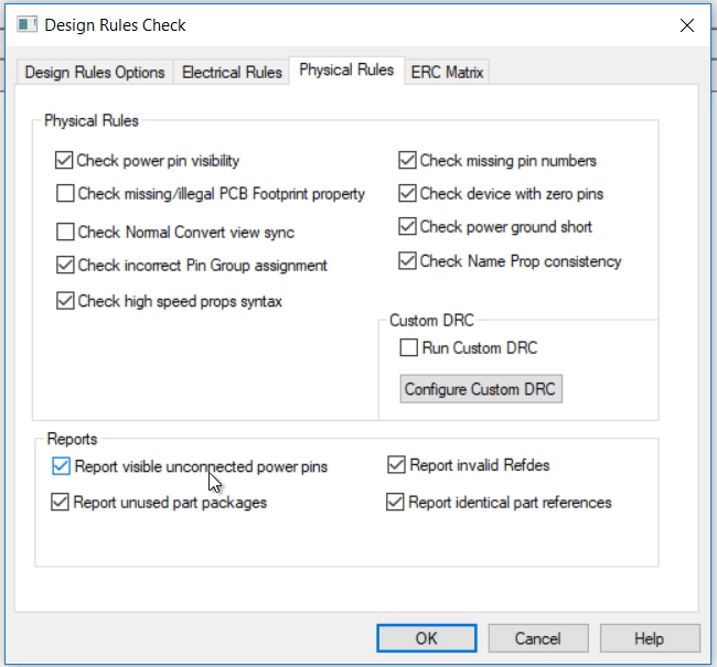
Design rule check in OrCAD X for Physical Rules
DRC Rules for Layout
During the layout stage, DRC rules for layout will also check physical parameters such as:
- Trace width and spacing
- Via size and spacing
- Drill to board aspect ratio
- Outline to all pin pads
Incorporating DRC rules for layout into your EDA process can prevent issues during production, saving you time and money. We’ve only scratched the surface of the types of checks you can run to ensure manufacturability of your design before it hits the assembly lines. Fortunately, modern PCB design software walks you through many of the checks you can run on your designs. Check out Cadence’s suite of PCB design and analysis tools today.
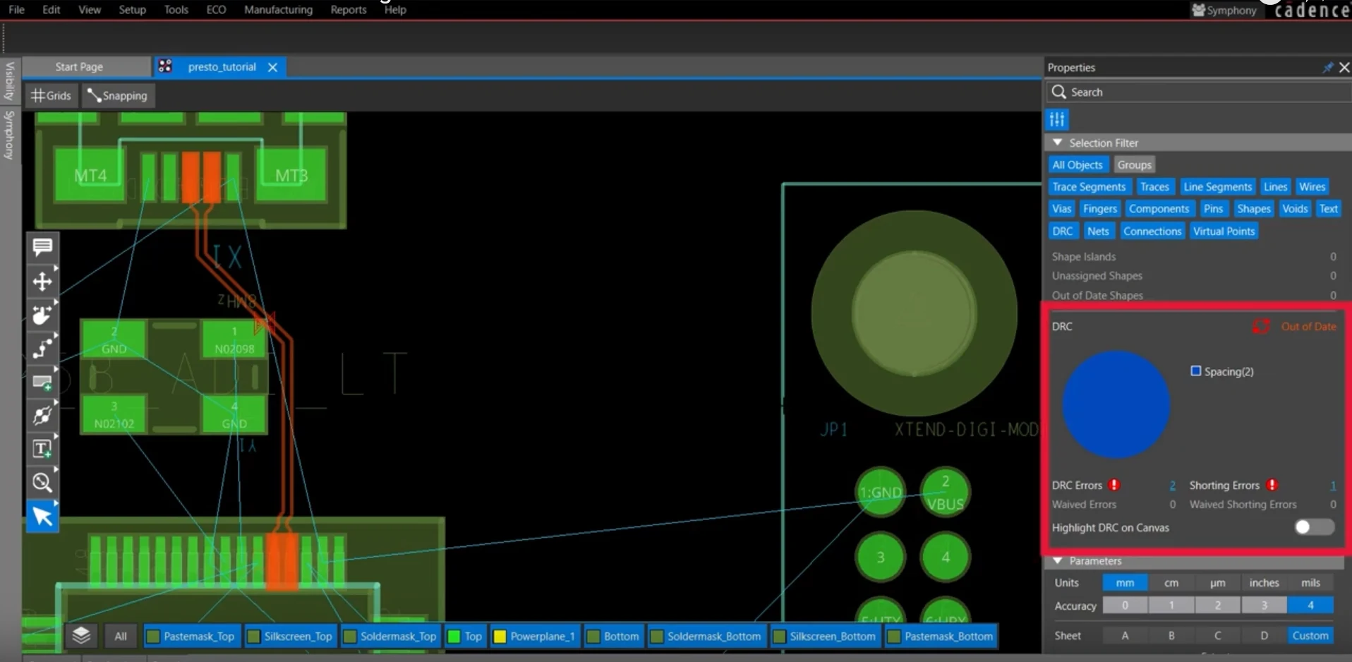
DRC status is reported in the pie chart within the OrCAD X Presto PCB Editor properties panel.
How OrCAD X Works With DRC Rules
OrCAD X integrates numerous Design Rule Check (DRC) features to ensure manufacturability of PCB layouts. It allows users to configure electrical, physical, and simulation rules, managing them through the constraint manager.
- Online DRCs check rules in real-time, while batch DRCs run during the design rule check process, helping to quickly identify and correct design violations
- DRC markers indicate areas of concern, which can be addressed by either correcting the design or waving the DRCs to update the error list.
- The tool also supports interactive features such as zooming into specific errors and using real-time feedback during routing to avoid violations.
- OrCAD X includes a properties panel that provides an overview of DRC violations, displayed as an interactive pie chart for easy navigation and correction of errors. This panel allows users to filter errors, such as spacing or physical violations, and correct them directly within the design canvas
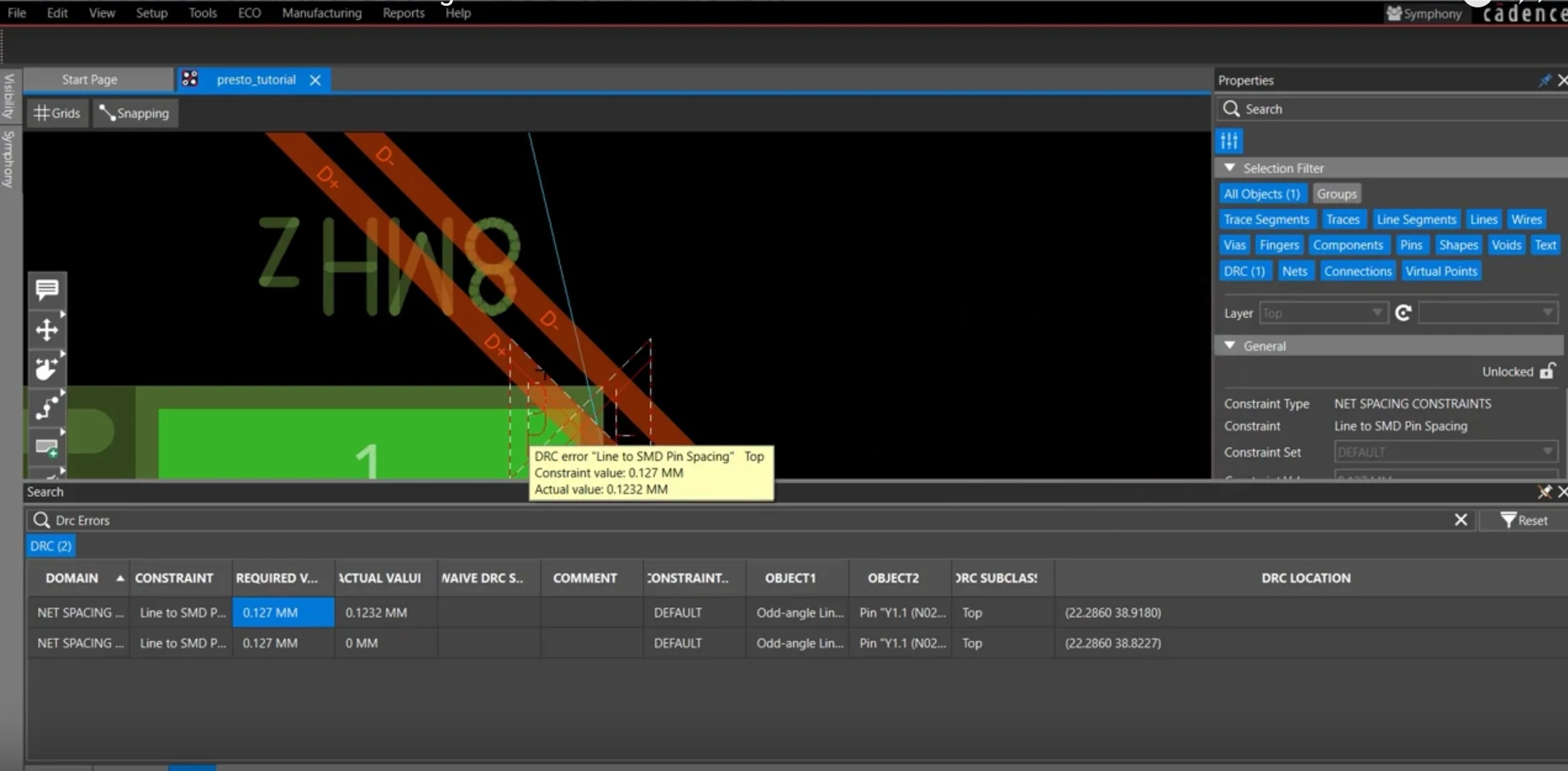
You can double-click a DRC error in the search bar to immediately be brought to where it is in the layout.
Performing a design rule check in PCB design is crucial to ensure your schematic adheres to dimensional tolerances and manufacturing standards, preventing costly production errors. Learn more about how Cadence can elevate your PCB design process by exploring our PCB Design and Analysis Software and discover the full potential of OrCAD X.
Leading electronics providers rely on Cadence products to optimize power, space, and energy needs for a wide variety of market applications. To learn more about our innovative solutions, talk to our team of experts or subscribe to our YouTube channel.