Calibration Step
inspectAR 2.0 calibration is a quick process you will need to complete in order to view your board in AR. The process is simple, you take a picture of the top and bottom of your board and then confirm to the software where the board edges are.
Full Board:
Preparing the Board for Calibration
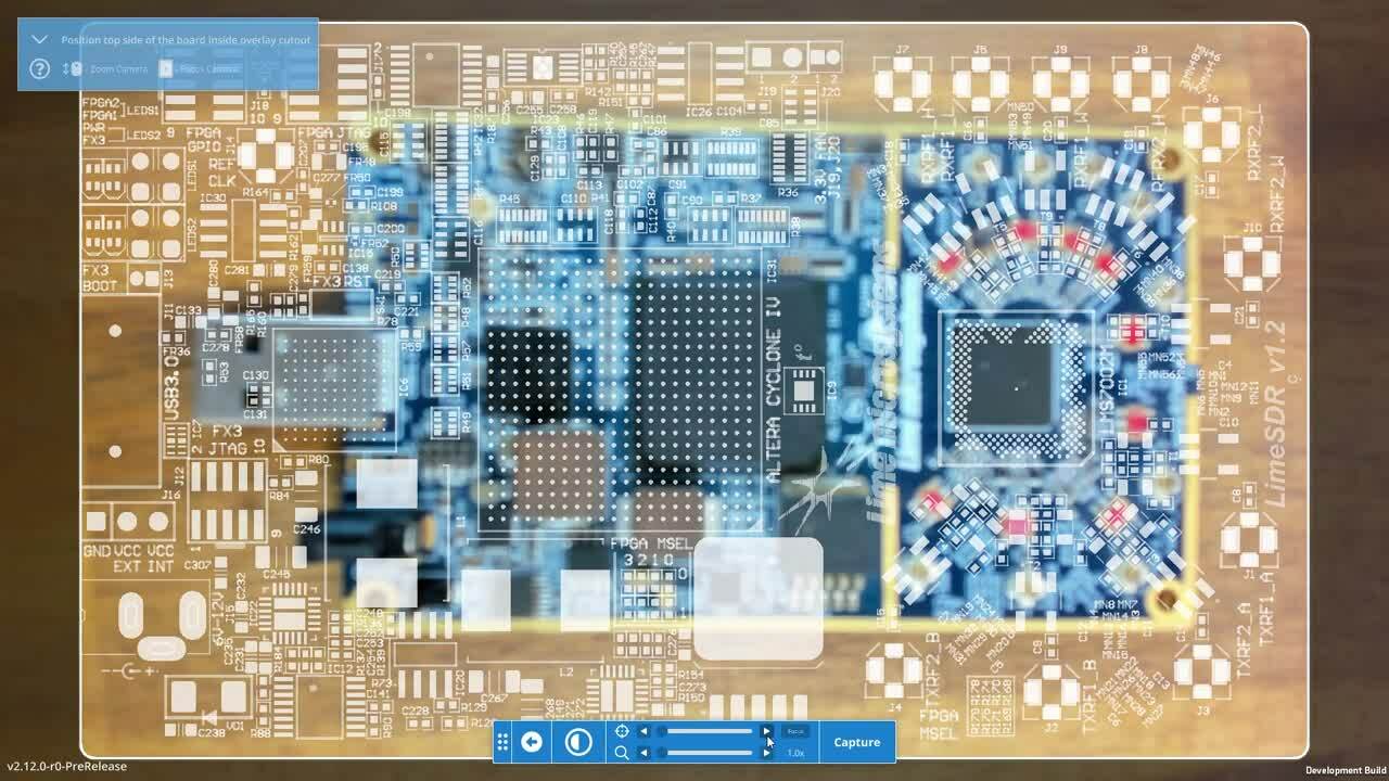
Upon launching the calibration scene you will see a semi-transparent image of your board's solder mask layer as shown below. There are five buttons in the toolbar to the right of the screen.
Exit to Dashboard on the top right will return you to the dashboard scene where you can select another project or a different camera.
Question Mark will show a tutorial video explaining the process of PCB calibration.
Capture (shutter) will capture an image (expect 2-3s exposure time while our algorithm runs).
Half Moon represents the transparency of the solder mask layer, it is set to 50% by default (half moon) and can be toggled to 100% (full moon) and 0% (dark moon). This is useful to help you find a fiducial to align your board onto.
Focus on the bottom right, this indicator will toggle between manual and automatic focus, if you cannot find focus in automatic mode, or your focus is unstable, use manual mode as shown below:
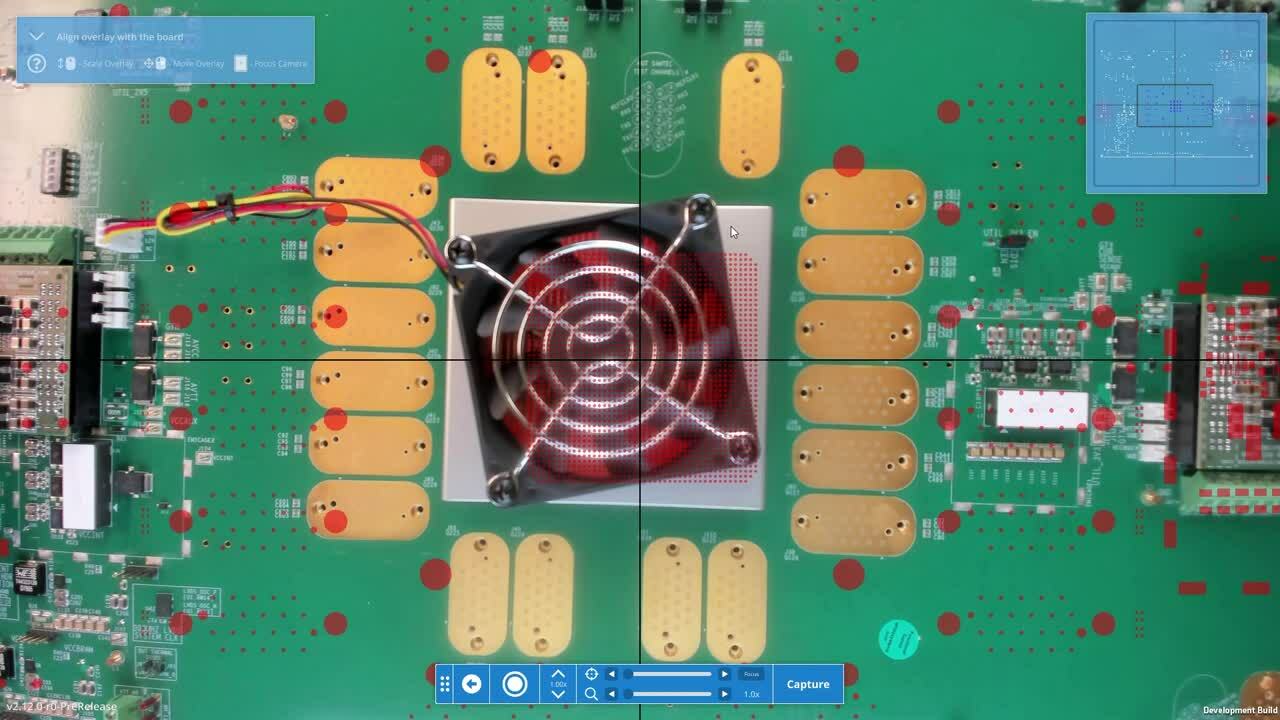
Aligning the Board Outline
Upon pressing the capture button the inspectAR tool will process for a few seconds while it tries to find the software's best guess at where the edges of your board are. You can then interact with this initial guess so that the real world edges of your board's outline align with the camera space which you are now operating in. As shown below, the tool can make a very accurate initial guess which you then only need a minor tweak. The quality of this initial guess depends on several environmental factors which ultimately affect the performance of your calibration.
The environmental factors which affect the quality of a calibration are:
Glare/Shadows
These are caused by directional light hitting your board. By diffusing your light sources or reducing their intensity you can reduce the glare and shadows present on your board. The resulting calibration will have more variance to movement and rotation as you are working with your board.
- Example: You are using a PCB mounted in a small board vice to do hand assembly and some multimeter continuity checks. The calibration without glare will show good alignment and stable, low-jitter tracking as you turn the vice to probe and solder.
- Blog: For best practices adjusting lighting to reduce glare, check out our in depth blog.
Image Texture
Image texture is an innate quality that images with lots of lines and corners perform better with augmented reality than those that are mostly flat. What do we mean by this? A blank sheet of paper in any colour is a completely textureless image whereas a checkerboard patterned image is more textured. More checkers equals more texture.
Textured images, lowest to highest
The lines and corners forming the black and white squares act like anchor points which our software can use to display PCB design information. In practice, things on your board like pads, silk screen, components, and info stickers provide these anchors which we automatically detect.
If you are having trouble getting a good calibration, try to make sure the background of your image is as flat as possible with the PCB in the foreground. If your board has a particularly sparse layout add some texture in between components. The labels of a Digi-Key bag or some random stickers you have lying around work great.
- Example: You have a bare unpopulated board which you are trying to calibrate. The overlays are misaligned and jittery. Add some texture into the sparse area to give inspectAR more points to anchor onto.
- Example: You calibrated your board on a different surface than the one you are working on. You notice some problems with the overlay quality. Try removing some texture from the images background so that inspectAR can focus on the texture in the foreground. Put a white sheet of paper, a black electrostatic mat, or any other plain colored surface under the board.
In this case, some of the texture in your images background (the grain of your oak desk for example) was distracting our algorithms from the texture on your board. Removing this texture will have things working like normal again.
Orthographic Alignment
Ideally your camera is parallel to the surface of your board while calibrating. Slight rotations should not be an issue, but if your board has an uneven surface on either the top or bottom, consider a simple set of mechanical holes for threaded standoffs early in your design. If you are in a pinch, the three-pronged plastic pin used to hold a pizza together as it is delivered to your lab will keep the board at a level height if you stand it upside down.
- Example: The bottom of your PCB is flat but the top side has a number of uneven edge connectors like below. Standoffs, a small vice grip, or an inverted board table (available from your favorite pizza restaurant) will level out the board giving you good calibration results.
- Example: Your camera mount has been twisted somehow, simply re-align it to get an orthographic calibration.
Camera Height & Zoom
Keystoning is a situation where the PCB is within less than a single focal length of your camera. In this case, the lens of the camera will distort the image making the edges of a rectangular board appear to converge as shown by the image below.
If you notice keystoning while calibrating, raise the height of your camera relative to the board until they are parallel to each other as they should be. From there you can use camera zoom to try and bring the camera world board outline as close to the real world board as possible. This will improve the quality of inspectAR’s initial guess in finding the board outline.
Calibrating to a keystoned image will cause overlays to be misaligned everywhere except for the center of your board.
Aligning Your Board Outline
Depending on how close you were able to line up your solder mask board outline with the projected image in the previous step, the board outline may need major or minor manual adjustments to obtain a snug fit as shown below. Remember, you are calibrating so precisely that 200 um by 400 um components, you need to make sure the outline in your calibration matches up with the dominant board edge seen in your red board outline like below.
You can use the bottom button to toggle between vertical and horizontal translation of the corner points. This is useful if you are perfectly aligned on the vertical axis such as below but then need to align the horizontal axis. You can also toggle back and forth between locking the handles using the second button from the bottom. This will allow you to move the sides of your board outline as if you are resizing a rectangle in any drawing software. You can toggle between these locking options to get a very fine tuned alignment of your board outline. Above we used the lock y axis mode (red arrows) to align the vertical axes of the board and then the lock x axis mode (green arrows) to align the horizontal axes of the board.
Now flip and repeat this process on the reverse side of your board, flip it over right-to-left as if you were turning the page to a book and double check that you have the right orientation with your solder mask.